Lexus NX: Installation
INSTALLATION
PROCEDURE
1. INSTALL WINDSHIELD WASHER JAR ASSEMBLY (w/ Headlight Cleaner System)
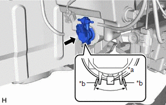
| (a) Install the level warning switch assembly as shown in the illustration. NOTICE: Make sure that the protrusion of the level warning switch assembly is between the 2 markings. |
|
.png)
(b) Install the headlight cleaner motor and pump.
(c) for Single Beam Headlight:
(1) Attach the claw to install the headlight cleaner control relay.
(2) Attach the guide to install the windshield washer jar assembly with the 3 bolts.
Torque:
5.5 N·m {56 kgf·cm, 49 in·lbf}
(3) Attach the 7 clamps and connect the 3 connectors.
(d) for Triple Beam Headlight:
(1) Attach the guide to install the windshield washer jar assembly with the 3 bolts.
Torque:
5.5 N·m {56 kgf·cm, 49 in·lbf}
(2) Attach the 7 clamps and connect the 2 connectors.
2. INSTALL WINDSHIELD WASHER JAR ASSEMBLY (w/o Headlight Cleaner System)
| (a) Install the level warning switch assembly as shown in the illustration. NOTICE: Make sure that the protrusion of the level warning switch assembly is between the 2 markings. |
|
(b) Attach the guide to install the windshield washer jar assembly with the 3 bolts.
Torque:
5.5 N·m {56 kgf·cm, 49 in·lbf}
(c) Attach the 7 clamps and connect the connector.
3. INSTALL WASHER INLET SUB-ASSEMBLY
(a) Install the washer inlet sub-assembly to the windshield washer jar assembly.
(b) Install the bolt.
Torque:
5.5 N·m {56 kgf·cm, 49 in·lbf}
4. INSTALL FRONT BUMPER COVER
(a) for Sport Package:
Click here .gif)
(b) except Sport Package:
Click here
5. INSTALL FRONT FENDER FRONT SPLASH SHIELD LH
Click here
6. INSTALL NO. 1 MOULDING TAPE
Click here
7. INSTALL NO. 2 MOULDING TAPE
Click here
8. INSTALL FRONT FENDER MOULDING SUB-ASSEMBLY LH
Click here
9. INSTALL RADIATOR GRILLE PROTECTOR
Click here
10. INSTALL RADIATOR SUPPORT OPENING COVER
Click here
11. INSTALL WINDSHIELD WASHER MOTOR AND PUMP ASSEMBLY
| (a) Install the windshield washer motor and pump assembly as shown in the illustration. NOTICE: Make sure that the protrusion of the windshield washer motor and pump assembly is between the 2 markings. |
|
(b) Connect the connector.
(c) Connect the rear washer hose.
12. FILL UP WINDSHIELD WASHER JAR AND PUMP ASSEMBLY WITH WASHER FLUID
(a) Connect the washer hose to the windshield washer motor and pump, and fill the washer jar with washer fluid.
13. INSTALL FRONT FENDER LINER RH
| (a) Install the front fender liner RH with the 6 clips and screw. |
|
.png)
| (b) Install the 2 new grommets. |
|
.png)
(c) Using a 4 mm hexagon wrench, install the hexagon screw.
14. INSTALL FRONT FENDER FRONT SPLASH SHIELD RH
HINT:
Use the same procedure described for the LH side.
Click here
15. INSTALL NO. 1 MOULDING TAPE
HINT:
Use the same procedure described for the LH side.
Click here
16. INSTALL NO. 2 MOULDING TAPE
HINT:
Use the same procedure described for the LH side.
Click here
17. INSTALL FRONT FENDER MOULDING SUB-ASSEMBLY RH
HINT:
Use the same procedure described for the LH side.
Click here
18. INSTALL FRONT WHEEL RH
Click here
READ NEXT:
 Washer Nozzle
ComponentsCOMPONENTS ILLUSTRATION *1 HOOD INSULATOR *2 WASHER NOZZLE SUB-ASSEMBLY *3 WASHER HOSE - - ● Non-reusable part - - On-vehicle InspectionON-VEHICLE INSPEC
Washer Nozzle(for Rear Side)
ComponentsCOMPONENTS ILLUSTRATION *1 REAR WASHER NOZZLE *2 REAR WASHER HOSE On-vehicle InspectionON-VEHICLE INSPECTION PROCEDURE 1. INSPECT REAR WASHER NOZZLE (a) With the power switch
SEE MORE:
Precaution
PRECAUTION PRECAUTION FOR DISCONNECTING CABLE FROM NEGATIVE AUXILIARY BATTERY TERMINAL NOTICE:
After turning the power switch off, waiting time may be required before disconnecting the cable from the negative (-) auxiliary battery terminal. Therefore, make sure to read the disconnecting the cable
Parts Location
PARTS LOCATION ILLUSTRATION *1 NO. 2 ENGINE ROOM RELAY BLOCK - DCM FUSE (w/ Manual [SOS] Switch) - ECU-B NO.5 FUSE - ECU-B NO.1 FUSE *2 NO. 1 ENGINE ROOM RELAY BLOCK - AMP FUSE - RADIO FUSE - METER NO.1 FUSE *3 TELEPHONE MICROPHONE ASSEMBLY *4 ROOF HEADLINING HOLDER COVER *5
