Lexus NX: Installation
INSTALLATION
PROCEDURE
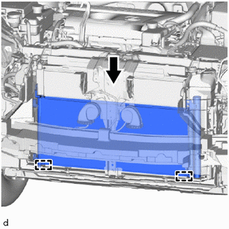
1. INSTALL COOLER CONDENSER ASSEMBLY
| (a) Attach the 2 guides to install the cooler condenser assembly. NOTICE: Do not damage the cooler condenser assembly or radiator assembly when installing the cooler condenser assembly. HINT: If the cooler condenser assembly is replaced with a new one, add compressor oil to the new cooler condenser assembly. Capacity: 40 cc (1.35 fl.oz) Compressor Oil: ND-OIL 11 or equivalent |
|
2. CONNECT LIQUID PIPE SUB-ASSEMBLY
(a) Remove the vinyl tape from the liquid pipe sub-assembly and the connecting part of the cooler condenser assembly.
(b) Sufficiently apply compressor oil to a new O-ring and the fitting surface of the liquid pipe sub-assembly.
Compressor Oil:
ND-OIL 11 or equivalent
(c) Install the O-ring to the liquid pipe sub-assembly.
NOTICE:
Keep the O-rings and O-ring fitting surfaces free of foreign matter.
(d) Connect the liquid pipe sub-assembly to the cooler condenser assembly with the bolt.
Torque:
5.4 N·m {55 kgf·cm, 48 in·lbf}
3. CONNECT DISCHARGE HOSE SUB-ASSEMBLY
(a) Remove the vinyl tape from the discharge hose sub-assembly and the connecting part of the cooler condenser assembly.
(b) Sufficiently apply compressor oil to a new O-ring and the fitting surface of the discharge hose sub-assembly.
Compressor Oil:
ND-OIL 11 or equivalent
(c) Install the O-ring to the discharge hose sub-assembly.
NOTICE:
Keep the O-rings and O-ring fitting surfaces free of foreign matter.
(d) Connect the discharge hose sub-assembly to the cooler condenser assembly with the bolt.
Torque:
5.4 N·m {55 kgf·cm, 48 in·lbf}
4. INSTALL RADIATOR ASSEMBLY
Click here .gif)
5. INSTALL FRONT BUMPER COVER
(a) for Sport Package:
Click here
(b) except Sport Package:
Click here
6. CHARGE AIR CONDITIONING SYSTEM WITH REFRIGERANT
Click here
7. WARM UP COMPRESSOR
Click here
8. INSPECT FOR REFRIGERANT LEAK
Click here
READ NEXT:
 Cooler Expansion Valve
ComponentsCOMPONENTS ILLUSTRATION *1 AIR CONDITIONER TUBE AND ACCESSORY ASSEMBLY *2 COOLER EXPANSION VALVE *3 O-RING - - N*m (kgf*cm, ft.*lbf): Specified torque ● Non
Front Blower Motor
ComponentsCOMPONENTS ILLUSTRATION *1 BLOWER WITH FAN MOTOR SUB-ASSEMBLY *2 NO. 2 INSTRUMENT PANEL UNDER COVER SUB-ASSEMBLY RemovalREMOVAL PROCEDURE 1. REMOVE NO. 2 INSTRUMENT PANEL UNDE
SEE MORE:
Thermostat (P0128)
DESCRIPTION This DTC is stored when the engine coolant temperature does not reach 73°C (163°F) despite sufficient engine warm-up time having elapsed. DTC No. Detection Item DTC Detection Condition Trouble Area MIL Memory P0128 Thermostat All of the following conditions are met
Power Supply Drive Circuit (C1257)
DESCRIPTION The skid control ECU (brake booster with master cylinder assembly) detects a drop in accumulator pressure according to the signals from the accumulator pressure sensor, then operates and stops the motor relay as well as the pump motor. The skid control ECU (brake booster with master cyli
