Lexus NX: Slide Sensor Malfunction (B2650)
DESCRIPTION
When the front power seat switch LH does not receive a sensor signal despite forward or backward movement of the seat by power seat motor operation, this DTC is stored.
| DTC No. | Detection Item | DTC Detection Condition | Trouble Area |
|---|---|---|---|
| B2650 | Slide Sensor Malfunction | The forward and backward lock detection position of the sensor is the same. |
|
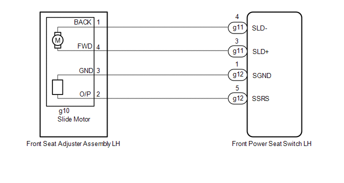
WIRING DIAGRAM
PROCEDURE
| 1. | CLEAR DTC |
(a) Clear the DTCs.
Click here .gif)
|
.gif)
| 2. | CHECK FOR DTC |
(a) Check for DTCs.
Click here
OK:
DTC B2650 is not output.
| OK | .gif) | USE SIMULATION METHOD TO CHECK |
|
| 3. | PERFORM ACTIVE TEST USING TECHSTREAM (SEAT SLIDE OPERATION) |
(a) Connect the Techstream to the DLC3.
(b) Turn the power switch on (IG).
(c) Turn the Techstream on.
(d) Enter the following menus: Body Electrical / Driver Seat / Active Test.
(e) Perform the Active Test according to the display on the Techstream.
Body Electrical > Driver Seat > Active Test| Tester Display | Measurement Item | Control Range | Diagnostic Note |
|---|---|---|---|
| Seat Slide Operation | Seat slide operation | OFF/Rear/Front | - |
| Tester Display |
|---|
| Seat Slide Operation |
OK:
Motor operates normally.
| NG | | GO TO STEP 11 |
|
| 4. | CHECK FRONT POWER SEAT SWITCH LH (SLIDE MOTOR CIRCUIT) |
| (a) Measure the voltage according to the value(s) in the table below. Standard Voltage:
|
|
| NG | | GO TO STEP 7 |
|
| 5. | CLEAR DTC |
(a) Clear the DTCs.
Click here
|
| 6. | CHECK FOR DTC |
(a) Check for DTCs.
Click here
OK:
DTC B2650 is not output.
| OK | | USE SIMULATION METHOD TO CHECK |
| NG | | REPLACE FRONT POWER SEAT SWITCH LH |
| 7. | CHECK HARNESS AND CONNECTOR (FRONT POWER SEAT SWITCH LH - FRONT SEAT ADJUSTER ASSEMBLY LH [SLIDE MOTOR]) |
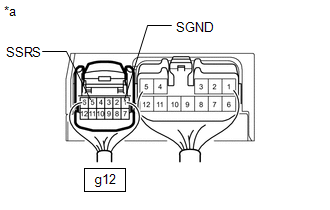
(a) Disconnect the g12 front power seat switch LH connector.
(b) Disconnect the g10 front seat adjuster assembly LH connector.
(c) Measure the resistance according to the value(s) in the table below.
Standard Resistance:
| Tester Connection | Condition | Specified Condition |
|---|---|---|
| g12-5 (SSRS) - g10-2 (O/P) | Always | Below 1 Ω |
| g12-5 (SSRS) or g10-2 (O/P) - Body ground | Always | 10 kΩ or higher |
| g12-1 (SGND) - g10-3 (GND) | Always | Below 1 Ω |
| g12-1 (SGND) or g10-3 (GND) - Body ground | Always | 10 kΩ or higher |
| NG | | REPAIR OR REPLACE HARNESS OR CONNECTOR |
|
| 8. | REPLACE FRONT POWER SEAT SWITCH LH |
(a) Replace the front seat switch LH with new or known good one.
Click here
|
| 9. | CLEAR DTC |
(a) Clear the DTCs.
Click here
|
| 10. | CHECK FOR DTC |
(a) Check for DTCs.
Click here
OK:
DTC B2650 is not output.
| OK | | END (FRONT POWER SEAT SWITCH LH WAS DEFECTIVE) |
| NG | | REPLACE FRONT SEAT ADJUSTER ASSEMBLY LH |
| 11. | INSPECT FRONT SEAT ADJUSTER ASSEMBLY LH (SLIDE MOTOR) |
(a) Remove the front seat adjuster assembly LH.
Click here
(b) Inspect the front seat adjuster assembly LH.
Click here
| NG | | REPLACE FRONT SEAT ADJUSTER ASSEMBLY LH |
|
| 12. | CHECK HARNESS AND CONNECTOR (FRONT POWER SEAT SWITCH LH - FRONT SEAT ADJUSTER ASSEMBLY LH [SLIDE MOTOR]) |
(a) Disconnect the g11 front power seat switch LH connector.
(b) Disconnect the g10 front seat adjuster assembly LH connector.
(c) Measure the resistance according to the value(s) in the table below.
Standard Resistance:
| Tester Connection | Condition | Specified Condition |
|---|---|---|
| g11-3 (SLD+) - g10-4 (FWD) | Always | Below 1 Ω |
| g11-3 (SLD+) or g10-4 (FWD) - Body ground | Always | 10 kΩ or higher |
| g11-4 (SLD-) - g10-1 (BACK) | Always | Below 1 Ω |
| g11-4 (SLD-) or g10-1 (BACK) - Body ground | Always | 10 kΩ or higher |
| OK | | REPLACE FRONT POWER SEAT SWITCH LH |
| NG | | REPAIR OR REPLACE HARNESS OR CONNECTOR |
READ NEXT:
 Short in Sensor with Motor Power Supply Circuit (B2658)
DESCRIPTION This DTC is stored when a power seat motor operates (a position control sensor is being supplied with power) and the power supply voltage does not rise to the specified value. DTC No.
Front Power Seat does not Operate with Front Power Seat Switch
DESCRIPTION Signals are input into the front power seat switch LH. The built-in ECU manages the signals received from the power seat switch, and operates each motor. If the front power seat switch LH
One or more Power Seat Motors do not Operate
DESCRIPTION Signals are input into the front power seat switch LH. The built-in ECU manages the signals received from the front power seat switch LH, and operates each motor. If the front power seat s
SEE MORE:
Installation
INSTALLATION PROCEDURE 1. INSTALL RAIN SENSOR TAPE NOTICE: The rain sensor tape is reusable. Only replace the tape if it is damaged or contaminated. (a) Clean the rain sensor sensing portion with a piece of cloth, etc. (b) Peel off the smaller release sheet, and then attach the rain sensor tape o
Removal
REMOVAL PROCEDURE 1. REMOVE DECK BOARD ASSEMBLY Click here 2. REMOVE NO. 3 DECK BOARD SUB-ASSEMBLY Click here 3. REMOVE REAR DECK FLOOR BOX Click here 4. REMOVE DECK FLOOR BOX LH Click here 5. PRECAUTION CAUTION: Be sure to read Precaution thoroughly before serving. Click here NOTICE: Afte
