Lexus NX: Installation
Lexus NX Service Manual / Vehicle Interior / Meter / Gauge / Display / Light Control Rheostat / Installation
INSTALLATION
PROCEDURE
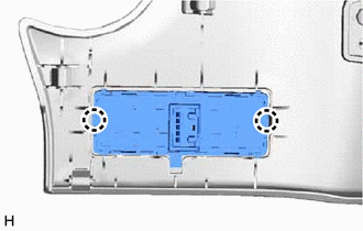
1. INSTALL TRIP SWITCH (LIGHT CONTROL RHEOSTAT)
| (a) Attach the 2 claws to install the trip switch (light control rheostat). |
|
2. INSTALL NO. 1 INSTRUMENT PANEL SAFETY PAD SUB-ASSEMBLY
Click here .gif)
3. INSTALL INSTRUMENT SIDE PANEL LH
Click here
READ NEXT:
 Precaution
PRECAUTION FUEL RECEIVER GAUGE OPERATION (a) OPERATION The combination meter assembly uses the fuel injection volume signal from the ECM, fuel sender gauge assembly to detect the amount of fuel remain
Parts Location
PARTS LOCATION ILLUSTRATION *A w/ Memory *B for Triple Beam Headlight *1 OUTER REAR VIEW MIRROR ASSEMBLY RH - SIDE TURN SIGNAL LIGHT ASSEMBLY RH *2 OUTER REAR VIEW MIRROR ASSEMBLY
SEE MORE:
Motor Rotation Angle Sensor (C1528)
DESCRIPTION The motor rotation angle sensor detects the motor rotation angle and sends this information to the power steering ECU assembly. DTC No. Detection Item DTC Detection Condition Trouble Area Warning Indicate Return-to-normal Condition C1528 Motor Rotation Angle Sensor M
Data List / Active Test
DATA LIST / ACTIVE TEST DATA LIST NOTICE: In the table below, the values listed under "Normal Condition" are reference values. Do not depend solely on these reference values when deciding whether a part is faulty or not. HINT: Using the Techstream to read the Data List allows the values or states of
© 2016-2026 Copyright www.lexunx.com
