Lexus NX: Installation
INSTALLATION
PROCEDURE
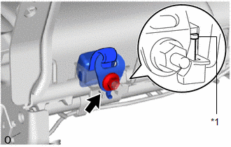
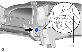
1. INSTALL REAR SEAT CENTER LAP TYPE BELT ASSEMBLY LH
| (a) Install the rear seat center lap type belt assembly LH with the nut. Torque: 42 N·m {428 kgf·cm, 31 ft·lbf} NOTICE: The anchor part of the rear seat center lap type belt assembly LH must not overlap the protruding part. |
|
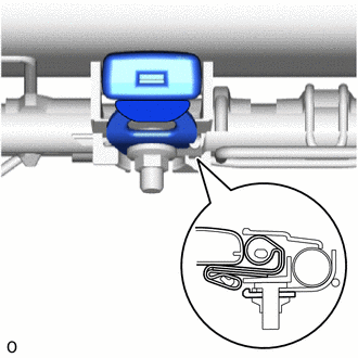
| (b) Install the rear seat center lap type belt assembly LH to the rear seat belt holder. |
|
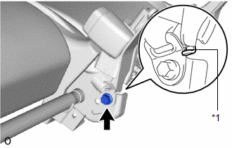
2. INSTALL REAR SEAT INNER BELT ASSEMBLY LH
(a) Attach the 2 hooks.
| (b) Install the rear seat inner belt assembly LH with the bolt. NOTICE: The anchor part of the rear seat inner belt assembly LH must not overlap the protruding part. Torque: 42 N·m {428 kgf·cm, 31 ft·lbf} |
|
| (c) for Manual Seat: (1) w/o Seat Heater System:
(2) w/ Seat Heater System:
|
|
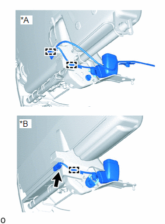
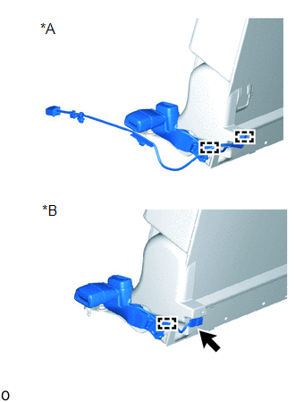
(d) for Power Seat:
| (1) Connect the connector. |
|
.png)
(2) Attach the wire harness clamp.
3. INSTALL REAR SEAT INNER WITH CENTER BELT ASSEMBLY RH
(a) Attach the 2 hooks.
| (b) Install the rear seat inner with center belt assembly RH with the bolt. Torque: 42 N·m {428 kgf·cm, 31 ft·lbf} NOTICE: The anchor part of the rear seat inner with center belt assembly RH must not overlap the protruding part. |
|
| (c) for Manual Seat: (1) w/o Seat Heater System:
(2) w/ Seat Heater System:
|
|
(d) for Power Seat:
| (1) Connect the connector. |
|
.png)
(2) Attach the wire harness clamp.
4. INSTALL REAR SEAT ASSEMBLY (for Manual Seat)
Click here .gif)
5. INSTALL REAR SEAT ASSEMBLY (for Power Seat)
Click here
READ NEXT:
 Components
COMPONENTS ILLUSTRATION *1 DECK FLOOR BOX LH *2 NO. 3 DECK BOARD SUB-ASSEMBLY *3 REAR DECK FLOOR BOX *4 NEGATIVE AUXILIARY BATTERY TERMINAL N*m (kgf*cm, ft.*lbf): Specified
Removal
REMOVAL CAUTION / NOTICE / HINT HINT:
Use the same procedure for the RH and LH sides.
The procedure listed below is for the LH side.
PROCEDURE 1. PRECAUTION NOTICE: After the power switch is t
SEE MORE:
Installation
INSTALLATION PROCEDURE 1. INSTALL NO. 5 ANTENNA CORD SUB-ASSEMBLY (a) Install the 2 grommets. (b) Attach the 3 clamps and install the washer hose to the clamp. (c) Connect the 4 connectors and install the No. 5 antenna cord sub-assembly. 2. INSTALL BACK DOOR TRIM BOARD ASSEMBLY Click here 3. INST
Occupant Classification System Malfunction (B1650)
DESCRIPTION The occupant classification system circuit consists of the airbag ECU assembly and occupant detection ECU. If the airbag ECU assembly receives signals from the occupant detection ECU, it determines whether the instrument panel passenger airbag, front seat airbag RH and front seat outer b
