Lexus NX: Installation
INSTALLATION
PROCEDURE
1. INSTALL ULTRASONIC SENSOR CUSHION SET
HINT:
Perform the following procedure only when replacement of a ultrasonic sensor cushion set is necessary.
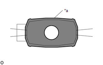
(a) Install the ultrasonic sensor cushion set as shown in the illustration.
.png)
.png) | Install in this Direction | - | - |
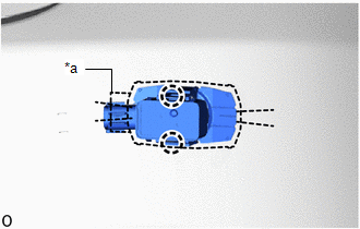
2. INSTALL REAR CORNER ULTRASONIC SENSOR RETAINER
NOTICE:
- Installing the rear corner ultrasonic sensor retainer with some double-sided tape remaining may cause poor adhesion. Perform this procedure until sufficiently removed it.
- Make sure to use a cloth when removing. Using a screwdriver, etc., may cause damage and poor adhesion.
HINT:
Use the same procedure for both rear corner ultrasonic sensor retainers.
(a) Clean the rear bumper cover surface.
(1) Remove the double-sided tape from the rear bumper cover.
(2) Wipe off any tape adhesive residue with cleaner.
| (b) Cover the sensor installation hole form the outside of the bumper cover with a 17 mm (0.67 in.) square piece of tape. |
|
.png)
(c) Using a brush or felt, apply primer or equivalent to the rear corner ultrasonic sensor retainer installation area.
NOTICE:
- Replace the brush or felt if it is dirty or has become hardened.
- Keep any painted surface free from primer.
- If the primer contacts a painted surface, it may leave light primer marks. Therefore, use protective tape when using liquid primer.
- Do not touch surfaces to which primer has been applied until the rear corner ultrasonic sensor retainer has been attached.
| *a | Scribed Line |
.png) | Primer |
HINT:
Primer application outside of the scribed line is acceptable.
(d) Let the primer dry sufficiently.
NOTICE:
Do not touch applied surfaces until the primer is dried.
Recommended drying time:
10 minutes or more (23°C (73°F))
(e) Confirm that the primer has completely dried by touching the rear bumper assembly. Then remove the tape.
(f) Remove the peeling paper of a new rear corner ultrasonic sensor retainer trying not to touch the adhesion surface.
| (g) Align the rear corner ultrasonic sensor retainer with the scribed line on the rear bumper assembly and install it as shown in the illustration. NOTICE:
HINT:
|
|
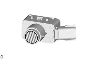
3. INSTALL REAR CORNER ULTRASONIC SENSOR
HINT:
- Use the same procedure for both rear corner ultrasonic sensors.
- When reusing the sensor, make sure that each sensor is returned to its original position.
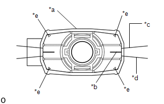
| (a) Align the connector of the rear corner ultrasonic sensor with the scribed line of rear bumper connector and set the rear corner ultrasonic sensor retainer. |
|
(b) Attach the 2 claws to install the rear corner ultrasonic sensor.
NOTICE:
- Check that the claw is securely fitted.
-
Do not push microphone surface.
.png)
Microphone Surface
4. INSTALL REAR CENTER ULTRASONIC SENSOR RETAINER
HINT:
Use the same procedure described for the rear corner ultrasonic sensor retainer.
5. INSTALL REAR CENTER ULTRASONIC SENSOR
HINT:
Use the same procedure described for the rear corner ultrasonic sensor.
6. INSTALL NO. 2 LUGGAGE ROOM WIRE
Click here .gif)
7. INSTALL REAR BUMPER COVER
Click here
8. PERFORM CALIBRATION
SST: 09989-00020
Click here
READ NEXT:
 Precaution
PRECAUTION WHEN DISCONNECTING AUXILIARY BATTERY CABLE (a) After the power switch is turned off, the radio receiver assembly requires approximately 6 minutes to record various types of memory and setti
SEE MORE:
Dtc Check / Clear
DTC CHECK / CLEAR DTC CHECK USING TECHSTREAM (a) Connect the Techstream to the DLC3. (b) Turn the power switch on (IG). (c) Turn the Techstream on. (d) Enter the following menus: Body Electrical / Air Conditioner / Trouble Codes. (e) Check for DTCs. Click here Body Electrical > Air Conditioner &
Installation
INSTALLATION PROCEDURE 1. INSTALL RAIN SENSOR TAPE NOTICE: The rain sensor tape is reusable. Only replace the tape if it is damaged or contaminated. (a) Clean the rain sensor sensing portion with a piece of cloth, etc. (b) Peel off the smaller release sheet, and then attach the rain sensor tape o
