Lexus NX: Removal
REMOVAL
CAUTION / NOTICE / HINT
NOTICE:
While the auxiliary battery is connected, even if the power switch is off, the brake control system activates when the brake pedal is depressed or any door courtesy switch turns on. Therefore, when servicing the brake system components, do not operate the brake pedal or open/close the doors while the auxiliary battery is connected.
PROCEDURE
1. REMOVE NO. 3 DECK BOARD SUB-ASSEMBLY
Click here .gif)
2. REMOVE REAR DECK FLOOR BOX
Click here
3. REMOVE DECK FLOOR BOX LH
Click here
4. PRECAUTION
CAUTION:
Be sure to read Precoution thoroughly before serving.
Click here
NOTICE:
After turning the power switch off, there may be a waiting time before disconnecting the negative (-) auxiliary battery terminal.
Click here
5. DISABLE BRAKE CONTROL
Click here
6. DRAIN BRAKE FLUID
NOTICE:
Wash off brake fluid immediately if it comes in contact with any painted surface.
7. REMOVE AIR CLEANER CASE SUB-ASSEMBLY
Click here
8. REMOVE BRAKE BOOSTER WITH MASTER CYLINDER ASSEMBLY
Click here
9. DISCONNECT HEATER ACCESSORY ASSEMBLY
| (a) Disconnect the connector. |
|
(b) Detach the clamp.
(c) Remove the 3 bolts and nut and disconnect the heater accessory assembly.
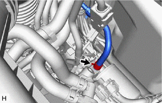
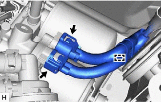
10. DISCONNECT NO. 1 BRAKE ACTUATOR HOSE
| (a) Slide the clip and disconnect the No. 1 brake actuator hose from the brake booster pump assembly. |
|
11. DISCONNECT FRONT NO. 1 BRAKE TUBE
| (a) Using a union nut wrench, disconnect the front No. 1 brake tube from the brake booster pump assembly. |
|
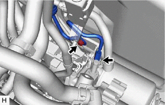
(b) Remove the bolt and disconnect the front No. 1 brake tube from the No. 1 brake clamp bracket.
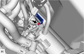
12. REMOVE NO. 1 BRAKE TUBE CLAMP BRACKET
| (a) Remove the bolt and No. 1 brake tube clamp bracket from the brake booster pump assembly. |
|
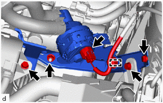
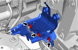
13. REMOVE BRAKE BOOSTER PUMP ASSEMBLY WITH BRACKET
| (a) Disconnect the 2 connectors and detach the clamp from the brake booster pump assembly. |
|
(b) Detach the brake tube clamp from the brake actuator bracket assembly.
| (c) Remove the 3 nuts and brake booster pump assembly with bracket. |
|
14. REMOVE BRAKE BOOSTER PUMP ASSEMBLY
| (a) Remove the 2 nuts, 2 brake booster pump bushings, 2 brake actuator case collars and brake booster pump assembly from the brake actuator bracket assembly. NOTICE:
|
|
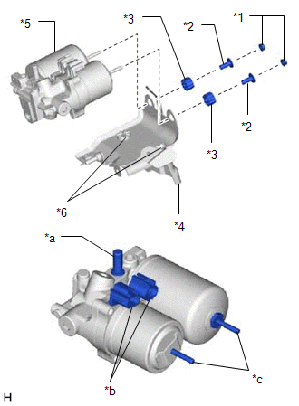
(b) Remove the 2 brake actuator bracket cushions from the brake actuator bracket assembly.
READ NEXT:
 Inspection
INSPECTION PROCEDURE 1. INSPECT BRAKE BOOSTER PUMP ASSEMBLY (a) Measure the resistance according to the value(s) in the table below. Standard Resistance: Tester Connection Condition Specifi
Installation
INSTALLATION PROCEDURE 1. INSTALL BRAKE BOOSTER PUMP ASSEMBLY (a) Install the 2 brake actuator bracket cushions to the brake actuator bracket assembly. (b) Install the brake booster pump assembly,
Disposal
DISPOSAL PROCEDURE 1. DISPOSE OF BRAKE BOOSTER PUMP ASSEMBLY (a) Remove the accumulator from the brake booster pump assembly. (b) Secure the accumulator in a vise. (c) Using a hacksaw, make a cut i
SEE MORE:
Data List / Active Test
DATA LIST / ACTIVE TEST DATA LIST NOTICE: In the following table, the values listed under "Normal Condition" are reference values. Do not depend solely on these reference values when deciding whether a part is faulty or not. HINT: Using the Techstream to read the Data List allows the values or state
Precaution
PRECAUTION HANDLING PRECAUTIONS FOR SRS AIRBAG SYSTEM Click here HANDLING PRECAUTIONS FOR STEERING COLUMN (a) When handling the electric power steering column sub-assembly: (1) Avoid any impact to the electric power steering column sub-assembly, especially to the motor or torque sensor. Replace t
