Lexus NX: Installation
INSTALLATION
PROCEDURE
1. INSTALL PARKING BRAKE ACTUATOR ASSEMBLY LH
(a) Apply a light coat of lithium soap base glycol grease to the new O-ring.
(b) Install the O-ring to the rear disc brake cylinder assembly LH.
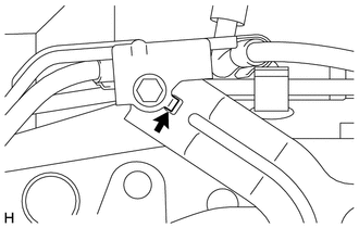
(c) Using a 5 mm hexagon socket wrench, install the parking brake actuator assembly LH with the 2 bolts.
Torque:
8.4 N·m {86 kgf·cm, 74 in·lbf}
2. INSTALL PARKING BRAKE WIRE ASSEMBLY NO.1
(a) Connect the connector to the parking brake wire assembly.
| (b) Insert the claw of the parking brake wire bracket into the groove of the support bracket. NOTICE: Make sure that the claws of the parking brake wire bracket are facing toward the rear of the vehicle during installation. |
|
(c) Install the parking brake wire bracket with the 4 bolts.
Torque:
6.0 N·m {61 kgf·cm, 53 in·lbf}
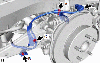
| (d) Install the parking brake wire assembly with the 2 bolts and nut, and then connect the connector to the parking brake actuator assembly LH. Torque: Bolt (A) : 10 N·m {102 kgf·cm, 7 ft·lbf} Bolt (B) : 6.0 N·m {61 kgf·cm, 53 in·lbf} Nut (C) : 16 N·m {163 kgf·cm, 12 ft·lbf} |
|
3. INSTALL REAR WHEEL
Click here .gif)
READ NEXT:
 Components
COMPONENTS ILLUSTRATION *1 DECK FLOOR BOX LH *2 NO. 3 DECK BOARD SUB-ASSEMBLY *3 REAR DECK FLOOR BOX *4 NEGATIVE AUXILIARY BATTERY TERMINAL N*m (kgf*cm, ft.*lbf): Specified
Removal
REMOVAL CAUTION / NOTICE / HINT NOTICE: While the auxiliary battery is connected, even if the power switch is off, the brake control system activates when the brake pedal is depressed or any door cour
SEE MORE:
Initialization
INITIALIZATION NOTICE:
The necessary procedures (adjustment, calibration, initialization or registration) that must be performed after parts are removed and installed, or replaced during headlight ECU sub-assembly LH removal/installation are shown below. Performed Work or System Condition Ne
System Description
SYSTEM DESCRIPTION OUTLINE OF COMBINATION METER ASSEMBLY *a Indication Example *b Hybrid System Indicator or Tachometer *c Speedometer *d
Power Condition
ODO/TRIP Meter
*e Engine Coolant Temperature Receiver Gauge *f Fuel Receiver Gauge *g Multi-informatio
