Lexus NX: Short to +B in Outer Mirror Indicator(Slave) (C1AB1)
DESCRIPTION
This DTC is stored when the blind spot monitor sensor RH detects a +B short in the outer rear view mirror indicator RH.
| DTC No. | Detection Item | DTC Detection Condition | Trouble Area | Note |
|---|---|---|---|---|
| C1AB1 | Short to +B in Outer Mirror Indicator(Slave) | Both of the following conditions are met:
|
| - |
WIRING DIAGRAM
w/o Retract Mirror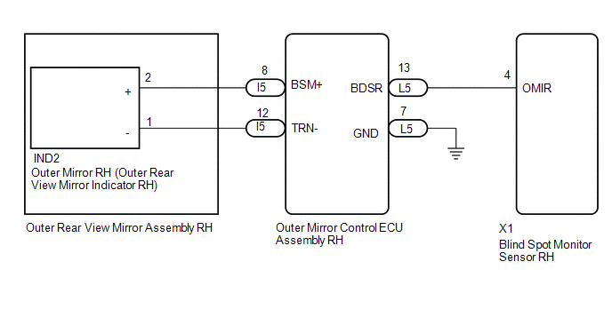 w/ Retract Mirror
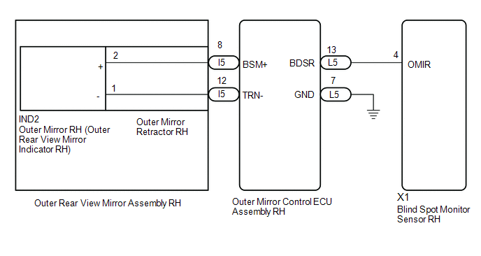
CAUTION / NOTICE / HINT
NOTICE:
When checking for DTCs, make sure that the blind spot monitor main switch (combination switch assembly) is on.
PROCEDURE
| 1. | CHECK DTC |
(a) Clear the DTCs.
Click here .gif)
(b) Recheck for DTCs and check if the same DTC is output again.
Body Electrical > Blind Spot Monitor Slave > Trouble CodesOK:
DTC C1AB1 is not output.
| OK | .gif) | USE SIMULATION METHOD TO CHECK |
|
.gif)
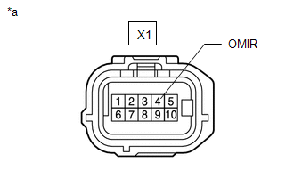
| 2. | CHECK HARNESS AND CONNECTOR (BLIND SPOT MONITOR SENSOR RH - OUTER MIRROR RH) |
| (a) Disconnect the blind spot monitor sensor RH connector. |
|
(b) Measure the voltage according to the value(s) in the table below.
Standard Voltage:
| Tester Connection | Switch Condition | Specified Condition |
|---|---|---|
| X1-4 (OMIR) - Body ground | Power switch on (IG) | Below 1 V |
| OK | | REPLACE BLIND SPOT MONITOR SENSOR RH |
|
| 3. | CHECK HARNESS AND CONNECTOR (BLIND SPOT MONITOR SENSOR RH - OUTER REAR VIEW MIRROR ASSEMBLY RH) |
| (a) Disconnect the blind spot monitor sensor RH connector. |
|
(b) Disconnect the IND2 outer mirror RH connector.
(c) Measure the voltage according to the value(s) in the table below.
Standard Voltage:
| Tester Connection | Switch Condition | Specified Condition |
|---|---|---|
| X1-4 (OMIR) - Body ground | Power switch on (IG) | Below 1 V |
| OK | | REPLACE OUTER MIRROR RH |
|
| 4. | CHECK HARNESS AND CONNECTOR (BLIND SPOT MONITOR SENSOR RH - OUTER MIRROR CONTROL ECU ASSEMBLY RH) |
| (a) Disconnect the blind spot monitor sensor RH connector. |
|
(b) Disconnect the l5 outer mirror control ECU assembly RH connector.
(c) Measure the voltage according to the value(s) in the table below.
Standard Voltage:
| Tester Connection | Switch Condition | Specified Condition |
|---|---|---|
| X1-4 (OMIR) - Body ground | Power switch on (IG) | Below 1 V |
| Result | Proceed to |
|---|---|
| OK (w/o Retract Mirror) | A |
| OK (w/ Retract Mirror) | B |
| NG | C |
| A | | REPLACE OUTER REAR VIEW MIRROR ASSEMBLY RH |
| B | | REPLACE OUTER MIRROR RETRACTOR RH |
|
| 5. | CHECK HARNESS AND CONNECTOR (BLIND SPOT MONITOR SENSOR RH - OUTER MIRROR CONTROL ECU ASSEMBLY RH) |
| (a) Disconnect the blind spot monitor sensor RH connector. |
|
(b) Disconnect the L5 outer mirror control ECU assembly RH connector.
(c) Measure the voltage according to the value(s) in the table below.
Standard Voltage:
| Tester Connection | Switch Condition | Specified Condition |
|---|---|---|
| X1-4 (OMIR) - Body ground | Power switch on (IG) | Below 1 V |
| OK | | REPLACE OUTER MIRROR CONTROL ECU ASSEMBLY |
| NG | | REPAIR OR REPLACE HARNESS OR CONNECTOR |
READ NEXT:
 Short to GND in Outer Mirror Indicator(Master) (C1AB2)
DESCRIPTION This DTC is stored when the blind spot monitor sensor LH detects a ground short in the outer rear view mirror indicator LH. DTC No. Detection Item DTC Detection Condition Trouble
Short to GND in Outer Mirror Indicator(Slave) (C1AB3)
DESCRIPTION This DTC is stored when the blind spot monitor sensor RH detects a ground short in the outer rear view mirror indicator RH. DTC No. Detection Item DTC Detection Condition Trouble
Open in Outer Mirror Indicator(Master) (C1AB4)
DESCRIPTION This DTC is stored when the blind spot monitor sensor LH detects an open in the outer rear view mirror indicator LH. DTC No. Detection Item DTC Detection Condition Trouble Area
SEE MORE:
Check For Intermittent Problems
CHECK FOR INTERMITTENT PROBLEMS CHECK FOR INTERMITTENT PROBLEMS HINT: A momentary interruption (open circuit) in the connectors and/or wire harnesses between the sensors and ECUs can be detected using the Data List function of the Techstream. (a) Turn the power switch off. (b) Connect the Techstream
Panel Switches do not Function
CAUTION / NOTICE / HINT NOTICE: When replacing the radio receiver assembly, always replace it with a new one. If a radio receiver assembly which was installed to another vehicle is used, the following may occur:
A communication malfunction DTC may be stored.
The radio receiver assembly may not
