Lexus NX: Removal
REMOVAL
CAUTION / NOTICE / HINT
NOTICE:
While the auxiliary battery is connected, even if the power switch is off, the brake control system activates when the brake pedal is depressed or any door courtesy switch turns on. Therefore, when servicing the brake system components, do not operate the brake pedal or open/close the doors while the auxiliary battery is connected.
PROCEDURE
1. REMOVE NO. 3 DECK BOARD SUB-ASSEMBLY
Click here .gif)
2. REMOVE REAR DECK FLOOR BOX
Click here
3. REMOVE DECK FLOOR BOX LH
Click here
4. PRECAUTION
CAUTION:
Be sure to read Precoution thoroughly before serving.
Click here
NOTICE:
After turning the power switch off, there may be a waiting time before disconnecting the negative (-) auxiliary battery terminal.
Click here
5. DISCONNECT CABLE FROM NEGATIVE AUXILIARY BATTERY TERMINAL
CAUTION:
- Wait at least 90 seconds after disconnecting the cable from the negative (-) auxiliary battery terminal to disable the SRS system.
- If the airbag deploys for any reason. it may cause a serious accident.
(a) Loosen the nut and disconnect the negative (-) auxiliary battery terminal.
6. REMOVE DECK TRIM SIDE PANEL ASSEMBLY LH
Click here
7. REMOVE PARKING BRAKE ECU ASSEMBLY
| (a) Disconnect the 3 connectors. |
|
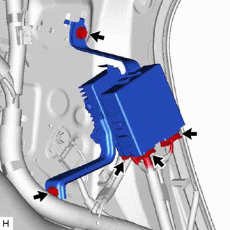
(b) Remove the 2 bolts and parking brake ECU assembly.
8. REMOVE FUEL PUMP CONTROL ECU ASSEMBLY
Click here
READ NEXT:
 Installation
INSTALLATION PROCEDURE 1. INSTALL FUEL PUMP CONTROL ECU ASSEMBLY Click here 2. INSTALL PARKING BRAKE ECU ASSEMBLY (a) Install the parking brake ECU assembly with the 2 bolts. Torque: 8.0 N·m {82 k
Components
COMPONENTS ILLUSTRATION *1 CENTER INSTRUMENT CLUSTER FINISH PANEL ASSEMBLY *2 INSTRUMENT SIDE PANEL LH *3 INSTRUMENT SIDE PANEL RH *4 LOWER NO. 1 INSTRUMENT PANEL FINISH PANEL
SEE MORE:
Removal
REMOVAL PROCEDURE 1. REMOVE FRONT SEAT ASSEMBLY LH Click here 2. REMOVE FRONT SEAT ASSEMBLY RH HINT: Use the same procedure as for the driver seat. 3. REMOVE FRONT SEAT INNER BELT ASSEMBLY LH (a) Disconnect the 2 connectors. (b) Detach the 6 clamps. (c) Detach the clamp.
Components
COMPONENTS ILLUSTRATION *A for 2WD *B for AWD *1 HOOD LOCK ASSEMBLY *2 NO. 6 INVERTER BRACKET *3 UPPER RADIATOR SUPPORT SUB-ASSEMBLY *4 FRONT RADIATOR SIDE AIR GUIDE PLATE RH *5 FRONT RADIATOR SIDE AIR GUIDE PLATE LH *6 WIRE HARNESS N*m (kgf*cm, ft.*lbf
