Lexus NX: Installation
INSTALLATION
CAUTION / NOTICE / HINT
HINT:
- Use the same procedure for the RH and LH sides.
- The procedure listed below is for the LH side.
PROCEDURE
1. INSTALL REAR DRIVE SHAFT ASSEMBLY LH
| (a) Align the matchmarks on the rear drive shaft assembly LH and rear axle hub and bearing assembly, and then insert the rear drive shaft assembly LH to the rear axle hub and bearing assembly. NOTICE:
|
|
.png)
| (b) Align the matchmarks on the rear drive shaft assembly LH and differential side gear shaft sub-assembly. |
|
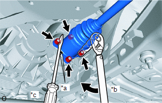
(c) Using a screwdriver or an equivalent, hold the differential side gear shaft sub-assembly as shown in the illustration.
NOTICE:
- Do not damage the inboard joint boot.
- Do not drop the rear drive shaft assembly LH.
(d) Install the rear drive shaft assembly LH with the 4 nuts and 4 washers.
Torque:
56 N·m {571 kgf·cm, 41 ft·lbf}
2. INSTALL REAR SUSPENSION ARM COVER LH
Click here .gif)
3. INSTALL REAR AXLE SHAFT NUT LH
Click here
4. INSTALL TAIL EXHAUST PIPE ASSEMBLY
Click here
5. INSTALL REAR WHEEL
Click here
6. INSPECT AND ADJUST REAR WHEEL ALIGNMENT
Click here
7. INSPECT FOR EXHAUST GAS LEAK
READ NEXT:
 Components
COMPONENTS ILLUSTRATION *A for 8 Inch *B for 10.3 Inch *1 CENTER INSTRUMENT CLUSTER FINISH PANEL ASSEMBLY *2 INSTRUMENT PANEL FINISH PLATE *3 INSTRUMENT SIDE PANEL LH *4
SEE MORE:
Installation
INSTALLATION PROCEDURE 1. INSTALL CRUISE CONTROL MAIN SWITCH (a) Pass the wire harness under the rib as shown in the illustration. *1 Wire Harness *a Rib *b Guide Connector Screw (b) Attach the guide. (c) Temporarily install the cruise control main switch with the
Problem Symptoms Table
PROBLEM SYMPTOMS TABLE NOTICE:
Before replacing the hybrid vehicle control ECU, refer to Registration.
Click here
When replacing the millimeter wave radar sensor assembly, always replace it with a new one. If a millimeter wave radar sensor assembly which was installed to another vehicle is us
