Lexus NX: Installation
INSTALLATION
PROCEDURE
1. INSTALL NO. 3 MOTOR WATER JACKET COVER ASSEMBLY
Click here .gif)
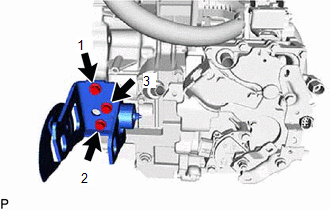
2. INSTALL NO. 1 MOTOR WATER JACKET COVER ASSEMBLY
Click here
3. INSTALL NO. 2 MOTOR WATER JACKET COVER ASSEMBLY
Click here
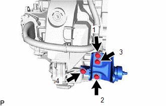
4. INSTALL MOTOR CONNECTOR PROTECTOR
(a) Apply adhesive to the 2 stud bolts.
Adhesive:
Toyota Genuine Adhesive 1324, Three Bond 1324 or equivalent
| (b) Using an E7 "TORX" socket wrench, install the 2 stud bolts. Torque: 9.0 N·m {92 kgf·cm, 80 in·lbf} |
|
.png)
(c) Install the motor connector protector to the hybrid vehicle transaxle assembly with the 2 bolts.
Torque:
10 N·m {102 kgf·cm, 7 ft·lbf}
5. INSTALL UNION
| (a) Install a new O-ring and union to the hybrid vehicle transaxle assembly. Torque: 27 N·m {275 kgf·cm, 20 ft·lbf} |
|
.png)
6. INSTALL TRANSAXLE BREATHER PLUG
| (a) Install the transaxle breather plug to the hybrid vehicle transaxle assembly. Torque: 11.3 N·m {115 kgf·cm, 8 ft·lbf} |
|
.png)
7. INSTALL HYBRID TRANSMISSION MASS DAMPER
| (a) Install a new gasket and the hybrid transmission mass damper to the hybrid vehicle transaxle assembly. Torque: 39.2 N·m {400 kgf·cm, 29 ft·lbf} |
|
.png)
8. INSTALL NO. 3 AUTOMATIC TRANSMISSION CASE COVER
| (a) Install the No. 3 automatic transmission case cover to the hybrid vehicle transaxle assembly with the 2 bolts and attach a new clip. Torque: 7.0 N·m {71 kgf·cm, 62 in·lbf} |
|
.png)
9. INSTALL AUTOMATIC TRANSMISSION CASE COVER
| (a) Attach the 2 guides and install the automatic transmission case cover to the No. 3 automatic transmission case cover. |
|
.png)
| (b) Attach the 2 clamps, and then connect the motor cable. |
|
.png)
10. INSTALL NO. 2 AUTOMATIC TRANSMISSION CASE COVER
| (a) Install the No. 2 automatic transmission case cover to the hybrid vehicle transaxle assembly with the bolt and a new clip. Torque: 11.8 N·m {120 kgf·cm, 9 ft·lbf} |
|
.png)
11. INSTALL OIL COOLER TUBE CLAMP
| (a) Install the oil cooler tube clamp to the hybrid vehicle transaxle assembly with the 2 bolts. Torque: 11.8 N·m {120 kgf·cm, 9 ft·lbf} |
|
.png)
12. INSTALL SHIFT LEVER POSITION SENSOR
Click here
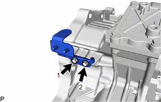
13. INSTALL NO. 1 TRANSMISSION CONTROL CABLE BRACKET
| (a) Install the No. 1 transmission control cable bracket to the hybrid vehicle transaxle assembly with the 2 bolts. Torque: 12 N·m {122 kgf·cm, 9 ft·lbf} |
|
.png)
14. INSTALL TRANSMISSION OIL COOLER BRACKET
(a) Temporarily install the transmission oil cooler bracket with the 2 bolts.
| (b) Tighten the 2 bolts in the sequence shown in the illustration. Torque: 8.2 N·m {84 kgf·cm, 73 in·lbf} |
|
15. INSTALL REAR ENGINE MOUNTING BRACKET
(a) Temporarily install the rear engine mounting bracket with the 4 bolts.
| (b) Tighten the 4 bolts in the sequence shown in the illustration. Torque: 45 N·m {459 kgf·cm, 33 ft·lbf} |
|
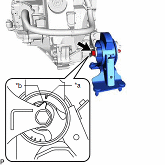
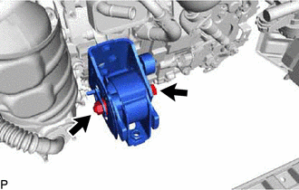
16. INSTALL REAR ENGINE MOUNTING INSULATOR
| (a) Install the rear engine mounting insulator with the through bolt and nut. Torque: 95 N·m {969 kgf·cm, 70 ft·lbf} HINT: When installing the rear engine mounting insulator, align the protrusion of the rear engine mounting bracket with the alignment mark of the rear engine mounting insulator. |
|
17. INSTALL ENGINE MOUNTING BRACKET LH
NOTICE:
The bolt has 2 types.
Bolt Length:| Item | Length |
|---|---|
| for Type A | 26.5 mm (1.04 in.) |
| for Type B | 25 mm (0.984 in.) |
| (a) for Type A: (1) Clean the bolts and the installation holes in the engine mounting bracket LH. (2) Apply adhesive to the 4 bolts. Adhesive: Toyota Genuine Adhesive 1324, Three Bond 1324 or equivalent (3) Temporarily install the engine mounting bracket LH with the 4 bolts. (4) Tighten the 4 bolts in the sequence shown in the illustration. Torque: 64 N·m {653 kgf·cm, 47 ft·lbf} |
|
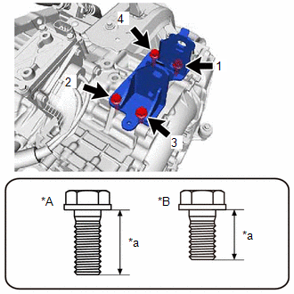
(b) for Type B:
(1) Temporarily install the engine mounting bracket LH with the 4 bolts.
(2) Tighten the 4 bolts in the sequence shown in the illustration.
Torque:
41 N·m {418 kgf·cm, 30 ft·lbf}
18. INSTALL NO. 3 OIL COOLER TUBE CLAMP
| (a) Install the No. 3 oil cooler tube clamp to the hybrid vehicle transaxle assembly with the bolt. Torque: 8.2 N·m {84 kgf·cm, 73 in·lbf} |
|
.png)
19. INSTALL FRONT ENGINE MOUNTING BRACKET
(a) Temporarily install the front engine mounting bracket with the 3 bolts.
| (b) Tighten the 3 bolts in the sequence shown in the illustration. Torque: 64 N·m {653 kgf·cm, 47 ft·lbf} |
|
20. TEMPORARILY INSTALL HYBRID VEHICLE TRANSAXLE ASSEMBLY
| (a) Make sure that the 2 knock pins are installed to the engine assembly. |
|
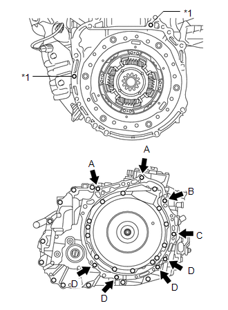
(b) Temporarily install the hybrid vehicle transaxle assembly to the engine assembly with the 8 bolts.
| Bolt | Bolt Length |
|---|---|
| A, B | 55 mm (2.17 in.) |
| C | 65 mm (2.56 in.) |
| D | 32 mm (1.26 in.) |
NOTICE:
- Do not apply grease either to the spline or to the input shaft assembly.
- Make sure that the wire harness or similar items are not pinched between the contact surfaces.
- Do not forcibly pry on the hybrid vehicle transaxle assembly.
- Make sure to align the hybrid vehicle transaxle assembly so that the input shaft assembly of the hybrid vehicle transaxle assembly will be inserted straight into the inner splines of the transmission input damper assembly.
- When inserting the input shaft assembly of the hybrid vehicle transaxle assembly into the inner splines of the transmission input damper assembly, do not shake the hybrid vehicle transaxle assembly excessively.
- When mounting the hybrid vehicle transaxle assembly to the engine assembly, make sure to securely fit the knock pins into the knock holes.
HINT:
Temporarily install bolt B first.
| (c) Temporarily install the engine mounting bracket LH with the through bolt and nut. |
|
.png)
21. INSTALL FRONT EXHAUST PIPE ASSEMBLY
Click here
22. TEMPORARILY INSTALL FRONT ENGINE MOUNTING INSULATOR
| (a) Temporarily install the front engine mounting insulator with the through bolt and nut. |
|
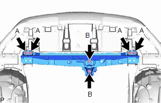
23. INSTALL FRONT CROSSMEMBER SUB-ASSEMBLY
| (a) Install the front crossmember sub-assembly with the 6 bolts. Torque: for Bolt A : 99 N·m {1010 kgf·cm, 73 ft·lbf} for Bolt B : 95 N·m {969 kgf·cm, 70 ft·lbf} |
|
24. TIGHTEN FRONT ENGINE MOUNTING INSULATOR
(a) Tighten the through bolt and nut of the front engine mounting insulator.
Torque:
145 N·m {1479 kgf·cm, 107 ft·lbf}
NOTICE:
While holding the nut in place, tighten the through bolt.
25. INSTALL FRONT SUSPENSION CROSSMEMBER SUB-ASSEMBLY
Click here
26. TIGHTEN ENGINE MOUNTING INSULATOR LH
(a) Tighten the through bolt and nut of the engine mounting insulator LH.
Torque:
56 N·m {571 kgf·cm, 41 ft·lbf}
27. REMOVE ENGINE SUPPORT BRIDGE
(a) Remove SST from the vehicle body.
NOTICE:
Prevent SST from contacting the vehicle body or windshield.
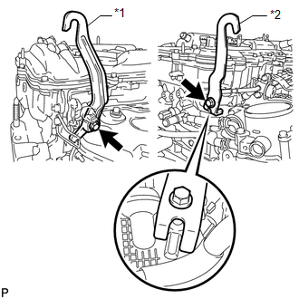
28. REMOVE ENGINE HANGER
| (a) Remove the 2 bolts, No. 1 engine hanger and No. 2 engine hanger. |
|
29. CONNECT RADIATOR RESERVE TANK ASSEMBLY
Click here
30. TIGHTEN HYBRID VEHICLE TRANSAXLE ASSEMBLY
| (a) Apply adhesive to the bolt E. Adhesive: Toyota Genuine Adhesive 1324, Three Bond 1324 or equivalent |
|
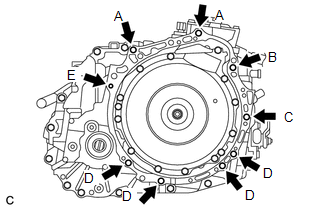
(b) Tighten the 9 bolts.
| Bolt | Bolt Length | Torque |
|---|---|---|
| A, B | 55 mm (2.17 in.) | 64 N*m (653 kgf*cm, 47 ft.*lbf) |
| C | 65 mm (2.56 in.) | 46 N*m (469 kgf*cm, 34 ft.*lbf) |
| D | 32 mm (1.26 in.) | 44 N*m (449 kgf*cm, 32 ft.*lbf) |
| E | 38 mm (1.50 in.) | 28 N*m (286 kgf*cm, 21 ft.*lbf) |
31. INSTALL FRONT DRIVE SHAFT ASSEMBLY
Click here
32. INSTALL NO. 2 TRANSMISSION CONTROL CABLE BRACKET
| (a) Install the No. 2 transmission control cable bracket to the hybrid vehicle transaxle assembly with the bolt. Torque: 12 N·m {122 kgf·cm, 9 ft·lbf} |
|
.png)
33. CONNECT TRANSMISSION CONTROL CABLE ASSEMBLY
Click here
34. CONNECT WIRE HARNESS
| (a) Connect the 7 clamps, 4 connectors and wire harness to the hybrid vehicle transaxle assembly. |
|
.png)
35. INSTALL NO. 3 INVERTER COOLING HOSE
Click here
36. INSTALL TRANSMISSION OIL COOLER ASSEMBLY
Click here
37. INSTALL AIR CLEANER CASE SUB-ASSEMBLY
Click here
38. INSTALL AIR CLEANER FILTER ELEMENT SUB-ASSEMBLY
Click here
39. INSTALL AIR CLEANER CAP AND HOSE
Click here
40. INSTALL NO. 1 ENGINE COVER SUB-ASSEMBLY
Click here
41. INSTALL OUTER COWL TOP PANEL
Click here
42. INSTALL SUSPENSION TOWER DAMPER
-
w/ Performance Damper:
Click here
-
w/o Performance Damper:
Click here
43. INSTALL WINDSHIELD WIPER MOTOR AND LINK ASSEMBLY
Click here
44. INSTALL SERVICE PLUG GRIP
Click here
45. ADD HYBRID TRANSAXLE FLUID
Click here
46. INSPECT HYBRID TRANSAXLE FLUID
Click here
47. INSPECT FOR EXHAUST GAS LEAK
Click here
48. INSPECT FOR FLUID LEAK
49. INSTALL NO. 1 ENGINE UNDER COVER ASSEMBLY
Click here
READ NEXT:
 Input Shaft Oil Seal
ComponentsCOMPONENTS ILLUSTRATION *1 HYBRID VEHICLE TRANSAXLE ASSEMBLY *2 INPUT SHAFT TYPE T OIL SEAL ● Non-reusable part MP grease ATF WS - - ReplacementREPLACE
Components
COMPONENTS ILLUSTRATION *1 NO. 1 ENGINE UNDER COVER ASSEMBLY - - ILLUSTRATION *1 FRONT ENGINE MOUNTING BRACKET *2 HYBRID VEHICLE TRANSAXLE ASSEMBLY *3 NO. 1 MOTOR WATER JA
SEE MORE:
Removal
REMOVAL PROCEDURE 1. REMOVE FRONT WIPER ARM HEAD CAP (a) Using a screwdriver, detach the 3 claws and remove the front wiper arm head cap. HINT:
Tape the screwdriver tip before use.
Use the same procedure for both front wiper arm head caps.
*1 Protective Tape 2. REM
ECM / PCM Processor (P0606)
MONITOR DESCRIPTION The ECM continuously monitors its main and sub CPUs. This self-check ensures that the ECM is functioning properly. If outputs from these CPUs are different and deviate from the standard, the ECM will illuminate the MIL and store this DTC. DTC No. Detection Item DTC Detecti
