- DTC judgment completed
- System normal
Lexus NX: Intake Air Temperature Sensor 1 Circuit Range / Performance (P0111)
Lexus NX Service Manual / Engine & Hybrid System / 2ar-fxe (engine Control) / Sfi System / Intake Air Temperature Sensor 1 Circuit Range / Performance (P0111)
DESCRIPTION
Refer to DTC P0112.
Click here .gif)
| DTC No. | Detection Item | DTC Detection Condition | Trouble Area | MIL | Memory |
|---|---|---|---|---|---|
| P0111 | Intake Air Temperature Sensor 1 Circuit Range / Performance | Either of the following conditions is met (2 trip detection logic):
| Mass air flow meter sub-assembly | Comes on | DTC stored |
MONITOR DESCRIPTION
The ECM performs OBD II monitoring based on the values from the intake air temperature sensor. If there is no change of the sensor value within the normal range, the ECM will not be able to perform OBD II monitoring or will misdiagnose that there is a malfunction in the sensor. The ECM detects when the intake air temperature sensor value is stuck by performing monitoring after the power switch is turned off or the engine is started (short soak or long soak).
MONITOR STRATEGY
| Related DTCs | P0111: Intake air temperature sensor rationality (After engine stop) P0111: Intake air temperature sensor rationality (After cold engine start) |
| Required Sensors/Components (Main) | Intake air temperature sensor |
| Required Sensors/Components (Related) | - |
| Frequency of Operation | Once per driving cycle |
| Duration | - |
| MIL Operation | 2 driving cycles |
| Sequence of Operation | None |
TYPICAL ENABLING CONDITIONS
All| Monitor runs whenever the following DTCs are not stored | None |
| All of the following conditions are met | - |
| Time after engine start | 10 seconds or more |
| Auxiliary battery voltage | 10.5 V or higher |
| Engine coolant temperature at ECM started by internal engine off timer | -40°C (-40°F) or higher |
| Engine coolant temperature before engine stop | 70°C (158°F) or higher |
| Accumulated mass air flow amount in previous driving cycle | 2305 g or more |
| Key-off duration | 30 minutes |
| Intake air temperature sensor circuit fail (P0112, P0113) | Not detected |
| Engine coolant temperature sensor circuit fail (P0115, P0117, P0118) | Not detected |
| Mass air flow meter circuit fail (P0102, P0103) | Not detected |
| Soak timer fail (P2610) | Not detected |
| All of the following conditions are met | - |
| Key-off duration | 5 hours or more |
| Time after engine start | 10 seconds or more |
| Engine coolant temperature | 70°C (158°F) or higher |
| Accumulated mass air flow amount | 2305 g or more |
| Either of the following conditions is met | 1 or 2 |
| 1. Duration while engine load is low | 120 seconds or more |
| 2. Duration while engine load is high | 10 seconds or more |
| Intake air temperature sensor circuit fail (P0112, P0113) | Not detected |
| Engine coolant temperature sensor circuit fail (P0115, P0117, P0118) | Not detected |
| Mass air flow meter circuit fail (P0102, P0103) | Not detected |
| Soak timer fail (P2610) | Not detected |
TYPICAL MALFUNCTION THRESHOLDS
After Engine Stop| Intake air temperature change | Less than 1°C (1.8°F) |
| Intake air temperature change | Less than 1°C (1.8°F) |
CONFIRMATION DRIVING PATTERN
- Connect the Techstream to the DLC3.
- Turn the power switch on (IG) and turn the Techstream on.
- Clear the DTCs (even if no DTCs are stored, perform the clear DTC procedure).
- Turn the power switch off and wait for at least 30 seconds.
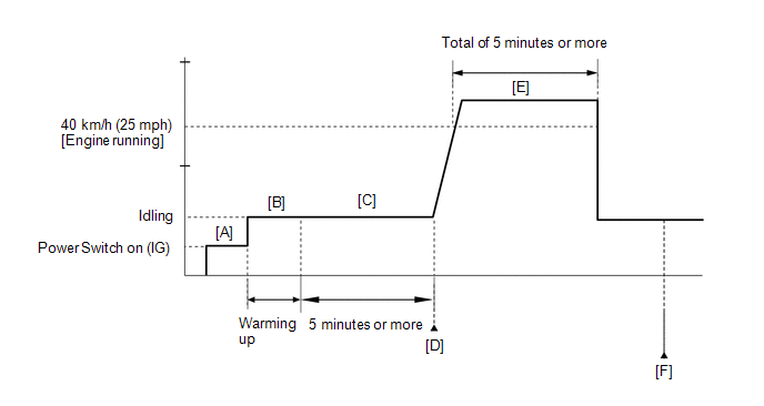
- Turn the power switch on (IG) and turn the Techstream on [A].
-
Put the engine in inspection mode (maintenance mode).
Click here
- Start the engine and warm it up until the engine coolant temperature reaches 75°C (167°F) or higher [B].
-
Idle the engine for 5 minutes or more [C].
HINT:
During steps [A] through [C], if the change in the intake air temperature is less than 1°C (1.8°F), the intake air temperature sensor (mass air flow meter sub-assembly) is malfunctioning. It is not necessary to continue this procedure.
- Enter the following menus: Powertrain / Engine and ECT / Trouble Codes [D].
-
Read the pending DTCs.
HINT:
- If a pending DTC is output, the system is malfunctioning.
- If a pending DTC is not output, perform the following procedure.
- Enter the following menus: Powertrain / Engine and ECT / Utility / All Readiness.
- Input the DTC: P0111.
-
Check the DTC judgment result.
Techstream Display
Description
NORMAL
ABNORMAL
- DTC judgment completed
- System abnormal
INCOMPLETE
- DTC judgment not completed
- Perform driving pattern after confirming DTC enabling conditions
N/A
- Unable to perform DTC judgment
- Number of DTCs which do not fulfill DTC preconditions has reached ECU memory limit
HINT:
- If the judgment result shows NORMAL, the system is normal.
- If the judgment result shows ABNORMAL, the system has a malfunction.
- If the judgment result shows INCOMPLETE or N/A, perform steps [E] and [F].
-
With the engine running, drive the vehicle at 40 km/h (25 mph) or more for a total of 5 minutes or more [E].
CAUTION:
When performing the confirmation driving pattern, obey all speed limits and traffic laws.
HINT:
If the engine stops, further depress the accelerator pedal to restart the engine.
-
Check the DTC judgment result again [F].
HINT:
If the judgment result shows INCOMPLETE or N/A, perform steps [E] and [F] again.
-
If no pending DTC is output, perform a universal trip and check for permanent DTCs.
Click here
HINT:
- If a permanent DTC is output, the system is malfunctioning.
- If no permanent DTC is output, the system is normal.
WIRING DIAGRAM
Refer to DTC P0112.
Click here
CAUTION / NOTICE / HINT
HINT:
Read freeze frame data using the Techstream. The ECM records vehicle and driving condition information as freeze frame data the moment a DTC is stored. When troubleshooting, freeze frame data can help determine if the vehicle was moving or stationary, if the engine was warmed up or not, if the air fuel ratio was lean or rich, and other data from the time the malfunction occurred.
PROCEDURE
| 1. | CHECK ANY OTHER DTCS OUTPUT (IN ADDITION TO DTC P0111) |
(a) Connect the Techstream to the DLC3.
(b) Turn the power switch on (IG).
(c) Turn the Techstream on.
(d) Enter the following menus: Powertrain / Engine and ECT / Trouble Codes.
(e) Read the DTCs.
Powertrain > Engine and ECT > Trouble Codes| Result | Proceed to |
|---|---|
| DTC P0111 and other DTCs are output | A |
| DTC P0111 is output | B |
HINT:
- If any DTCs other than P0111 are output, troubleshoot those DTCs first.
-
Perform "Inspection After Repair" after replacing the mass air flow meter sub-assembly.
Click here
| A | .gif) | GO TO DTC CHART |
| B | | REPLACE MASS AIR FLOW METER SUB-ASSEMBLY |
READ NEXT:
 Intake Air Temperature Circuit Low Input (P0112,P0113)
DESCRIPTION The intake air temperature sensor, mounted on the mass air flow meter sub-assembly, monitors the intake air temperature. The intake air temperature sensor has a built-in thermistor with a
Engine Coolant Temperature Circuit (P0115,P0117,P0118)
DESCRIPTION A thermistor, whose resistance value varies according to the engine coolant temperature, is built into the engine coolant temperature sensor. The structure of the sensor and its connection
Engine Coolant Temperature Circuit Range / Performance (P0116)
DESCRIPTION Refer to DTC P0115. Click here DTC No. Detection Item DTC Detection Condition Trouble Area MIL Memory P0116 Engine Coolant Temperature Circuit Range / Performance Ei
SEE MORE:
Inspection
INSPECTION PROCEDURE 1. INSPECT TRIP SWITCH *1 ODO TRIP Switch *a Component without harness connected (Trip Switch) (a) Check the resistance. Measure the resistance according to the value(s) in the table below. Standard Resistance: Tester Connection Switch Condition Specified
Components
COMPONENTS ILLUSTRATION *A for Driver Side *B for Front Passenger Side *1 FRONT DOOR INSIDE HANDLE BEZEL PLUG LH *2 FRONT DOOR TRIM BOARD SUB-ASSEMBLY LH *3 FRONT DOOR TRIM COVER LH *4 POWER WINDOW REGULATOR MASTER SWITCH ASSEMBLY WITH FRONT DOOR ARMREST BASE PANEL
© 2016-2026 Copyright www.lexunx.com
