- Inverter Coolant Water Temperature
- Inverter Temp- (MG2)
- Inverter Temp- (MG1)
- Rear Inverter Temp
- DC/DC Cnv Temp (Upper)
- DC/DC Cnv Temp (Lower)
- Inverter W/P Revolution
Lexus NX: Inverter Cooling System Performance (P0A93-346)
Lexus NX Service Manual / Engine & Hybrid System / 2ar-fxe (hybrid / Battery Control) / Hybrid Control System / Inverter Cooling System Performance (P0A93-346)
DTC SUMMARY
MALFUNCTION DESCRIPTION
This DTC indicates when the temperature inside the inverter has become abnormal. The cause of this malfunction may be one of the following:
Hybrid cooling system malfunction
- Coolant is leaking, insufficient coolant level, frozen or the passenger of coolant is clogged.
- Grille is blocked.
Internal inverter malfunction
- Inverter internal circuit malfunction
- Malfunction in ECU that controls the inverter
- Malfunction in sensor for inverter control (coolant sensor)
DESCRIPTION
Refer to the system description for the cooling system.
Click here .gif)
| DTC No. | Detection Item | DTC Detection Condition | Trouble Area | MIL | Warning Indicate |
|---|---|---|---|---|---|
| P0A93-346 | Inverter Cooling System Performance | Inverter coolant temperature increases as well as the temperature of any inverter with converter assembly related parts due to an inverter cooling system malfunction. (1 trip detection logic) |
| Comes on | Master Warning Light: Comes on |
| DTC No. | ECU Data List |
|---|---|
| P0A93-346 | |
MONITOR DESCRIPTION
If the hybrid vehicle control ECU detects a malfunction of the inverter cooling system, the ECU will illuminate the MIL and store a DTC.
MONITOR STRATEGY
| Related DTCs | P0A93 (INF 346): HV cooling system malfunction |
| Required sensors/components | Water pump, radiator fan, inverter, boost converter |
| Frequency of operation | Continuous |
| Duration | TMC's intellectual property |
| MIL operation | 1 driving cycle |
| Sequence of operation | None |
TYPICAL ENABLING CONDITIONS
| The monitor will run whenever the following DTCs are not stored | TMC's intellectual property |
| Other conditions belong to TMC's intellectual property | - |
TYPICAL MALFUNCTION THRESHOLDS
| TMC's intellectual property | - |
COMPONENT OPERATING RANGE
| Hybrid vehicle control ECU | DTC P0A93 (INF 346) is not detected |
CONFIRMATION DRIVING PATTERN
- Connect the Techstream to the DLC3.
- Turn the power switch on (IG) and turn the Techstream on.
- Clear the DTCs (even if no DTCs are stored, perform the clear DTC procedure).
- Turn the power switch off and wait for 30 seconds or more.
- Turn the power switch on (IG) and turn the Techstream on.
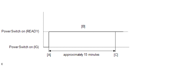
- Turn the power switch on (READY). [A]
-
Perform a road test according to the freeze frame data item "Vehicle Spd" for approximately 15 minutes. [B]
During the road test, check Data List items "Inverter Coolant Water Temperature", "Inverter Temp- (MG2)", "Inverter Temp- (MG1)", "DC/DC Cnv Temp (Upper)", " DC/DC Cnv Temp (Lower)" and "Engine Coolant Temp" to prevent them from overheating.
- Enter the following menus: Powertrain / Hybrid Control / Trouble Codes. [C]
-
Read the current DTCs.
HINT:
- If a current DTC is output, the system is malfunctioning.
- If current DTCs are not output, perform the following steps to check for permanent DTCs.
- Check that the permanent DTCs are cleared.
- If the permanent DTCs are not cleared, perform a universal trip, and then check for permanent DTCs again.
CAUTION / NOTICE / HINT
CAUTION:
- Before inspecting the high-voltage system or disconnecting the low voltage connector of the inverter with converter assembly, take safety precautions such as wearing insulated gloves and removing the service plug grip to prevent electrical shocks. After removing the service plug grip, put it in your pocket to prevent other technicians from accidentally reconnecting it while you are working on the high-voltage system.
-
After removing the service plug grip, wait for at least 10 minutes before touching any of the high-voltage connectors or terminals. After waiting for 10 minutes, check the voltage at the terminals in the inspection point in the inverter with converter assembly. The voltage should be 0 V before beginning work.
Click here
HINT:
Waiting for at least 10 minutes is required to discharge the high-voltage capacitor inside the inverter with converter assembly.
NOTICE:
-
After turning the power switch off, waiting time may be required before disconnecting the cable from the negative (-) auxiliary battery terminal. Therefore, make sure to read the disconnecting the cable from the negative (-) auxiliary battery terminal notices before proceeding with work.
Click here
- If DTC P0A78-284, 286, P0A79-692, 696, P0A7A-322, 324, P0A94-553 or 557 is output, replace the inverter with converter assembly after this inspection.
HINT:
After the repair, clear the DTCs and perform the following procedure to check that DTCs are not output.
-
Perform a road test according to the freeze frame data item "Vehicle Spd" for approximately 15 minutes.
During the road test, check Data List items "Inverter Coolant Water Temperature", "Inverter Temp-(MG2)", "Inverter Temp- (MG1)", "Rear Inverter Temp", "DC/DC Cnv Temp (Upper)" and " DC/DC Cnv Temp (Lower)" to prevent them from overheating.
PROCEDURE
| 1. | CHECK DTC OUTPUT (HYBRID CONTROL) |
(a) Connect the Techstream to the DLC3.
(b) Turn the power switch on (IG).
(c) Enter the following menus: Powertrain / Hybrid Control / Trouble Codes.
(d) Check for DTCs.
Powertrain > Hybrid Control > Trouble Codes| Result | Proceed to |
|---|---|
| P0A93-346 only is output, or DTCs except the ones in the table below are also output. | A |
| Any of the following DTCs are also output. | B |
| Relevant DTC | |
|---|---|
| P0A02-719 | Motor Electronics Coolant Temperature Sensor Circuit Low |
| P0A03-720 | Motor Electronics Coolant Temperature Sensor Circuit High |
| P0C73-776 | Motor Electronics Coolant Pump "A" Control Performance |
| P314A-828 | Inverter Coolant Pump Speed Signal |
HINT:
P0A93-346 may be output as a result of the malfunction indicated by the DTCs above.
(e) Turn the power switch off.
| B | .gif) | GO TO DTC CHART (HYBRID CONTROL SYSTEM) |
|
.gif)
| 2. | CHECK CONNECTOR CONNECTION CONDITION (INVERTER WITH CONVERTER ASSEMBLY CONNECTOR) |
Click here
| Result | Proceed to |
|---|---|
| OK | A |
| NG (The connector is not connected securely.) | B |
| NG (The terminals are not making secure contact or are deformed, or water or foreign matter exists in the connector.) | C |
| B | | CONNECT SECURELY |
| C | | REPAIR OR REPLACE HARNESS OR CONNECTOR |
|
| 3. | CHECK COOLING SYSTEM |
Click here
HINT:
If the "Cooling System" inspection results are normal, perform the next step.
| NEXT | | REPLACE INVERTER WATER PUMP ASSEMBLY |
READ NEXT:
 DC / DC Converter Performance (P0A94-127)
DTC SUMMARY MALFUNCTION DESCRIPTION This DTC indicates that an overvoltage in the inverter has occurred. The cause of this malfunction may be one of the following: Area Main Malfunction Descripti
DC / DC Converter Performance (P0A94-550,P0E32-564)
DTC SUMMARY MALFUNCTION DESCRIPTION These DTCs indicate a malfunction inside the inverter for the motor. The cause of this malfunction may be one of the following: Internal inverter malfunction
Int
DC / DC Converter Performance (P0A94-553)
DTC SUMMARY MALFUNCTION DESCRIPTION This DTC indicates when the temperature of the boost converter has become abnormal. The cause of this malfunction may be one of the following: Area Main Malfun
SEE MORE:
Inspection
INSPECTION PROCEDURE 1. INSPECT HV BATTERY JUNCTION BLOCK ASSEMBLY (a) Inspect SMRB: (1) Measure the resistance according to the value(s) in the table below. Standard Resistance: Tester Connection Condition Specified Condition x2-1 (+) - t5-1 (CBI) Auxiliary battery voltage not appl
Asc Speaker
ComponentsCOMPONENTS ILLUSTRATION *1 NO. 1 SPEAKER ASSEMBLY WITH BOX - - RemovalREMOVAL PROCEDURE 1. REMOVE CONSOLE BOX ASSEMBLY Click here 2. REMOVE NO. 1 SPEAKER ASSEMBLY WITH BOX (a) Remove the 4 bolts and disconnect the connector. (b) Detach the 2 claws used to t
© 2016-2026 Copyright www.lexunx.com
