Lexus NX: Main Switch Circuit
DESCRIPTION
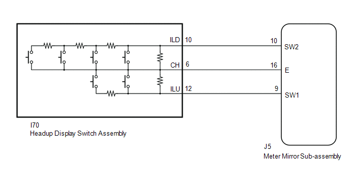
The headup display switch assembly and meter mirror sub-assembly are connected via direct line. The meter mirror sub-assembly can be turned off and on by operating the headup display switchassembly.
WIRING DIAGRAM
PROCEDURE
| 1. | READ VALUE USING TECHSTREAM (MAIN SWITCH) |
(a) Connect the Techstream to the DLC3.
(b) Turn the power switch on (IG).
(c) Turn the Techstream on.
(d) Enter the following menus: Body Electrical / Head Up Display / Data List.
(e) Read the Data List according to the display on the Techstream.
Body Electrical > Head Up Display > Data List| Tester Display | Measurement Item | Range | Normal Condition | Diagnostic Note |
|---|---|---|---|---|
| Main Switch | Main switch | OFF or ON | OFF: Switch released ON: Switch pushed | - |
| Brightness Up Switch | Brightness up switch | OFF or ON | OFF: Switch released ON: Switch pushed | - |
| Brightness Down Switch | Brightness down switch | OFF or ON | OFF: Switch released ON: Switch pushed | - |
| Projection Position Up Switch | Projection position up switch | OFF or ON | OFF: Switch released ON: Switch pushed | - |
| Projection Position Down Switch | Projection position down switch | OFF or ON | OFF: Switch released ON: Switch pushed | - |
| Display Change Switch | Display change switch | OFF or ON | OFF: Switch released ON: Switch pushed | - |
OK:
Headup display switch assembly condition displayed on the Techstream changes with the actual switch operation.
Body Electrical > Head Up Display > Data List| Tester Display |
|---|
| Main Switch |
| Brightness Up Switch |
| Brightness Down Switch |
| Projection Position Up Switch |
| Projection Position Down Switch |
| Display Change Switch |
| OK | .gif) | REPLACE METER MIRROR SUB-ASSEMBLY |
|
.gif)
| 2. | INSPECT HEADUP DISPLAY SWITCH ASSEMBLY |
(a) Remove the headup display switch assembly.
Click here .gif)
(b) Inspect the headup display switch assembly.
Click here
| NG | | REPLACE HEADUP DISPLAY SWITCH ASSEMBLY |
|
| 3. | CHECK HARNESS AND CONNECTOR (METER MIRROR SUB-ASSEMBLY - HEADUP DISPLAY SWITCH ASSEMBLY) |
(a) Disconnect the J5 meter mirror sub-assembly connector.
(b) Disconnect the I70 headup display switch assembly) connector.
(c) Measure the resistance according to the value(s) in the table below.
Standard Resistance:
| Tester Connection | Condition | Specified Condition |
|---|---|---|
| J5-9(SW1) - I70-12(ILU) | Always | Below 1 Ω |
| J5-10(SW2) - I70-10(ILD) | Always | Below 1 Ω |
| J5-16(E) - I70-6(CH) | Always | Below 1 Ω |
| J5-9(SW1) or I70-12(ILU) - Body ground | Always | 10 kΩ or higher |
| J5-10(SW2) or I70-10(ILD) - Body ground | Always | 10 kΩ or higher |
| J5-16(E) or I70-6(CH) - Body ground | Always | 10 kΩ or higher |
| OK | | REPLACE METER MIRROR SUB-ASSEMBLY |
| NG | | REPAIR OR REPLACE HARNESS OR CONNECTOR |
READ NEXT:
 Components
COMPONENTS ILLUSTRATION *1 INSTRUMENT SIDE PANEL LH *2 NO. 1 INSTRUMENT PANEL SAFETY PAD SUB-ASSEMBLY *3 TRIP SWITCH (LIGHT CONTROL RHEOSTAT) - -
Removal
REMOVAL PROCEDURE 1. REMOVE INSTRUMENT SIDE PANEL LH Click here 2. REMOVE NO. 1 INSTRUMENT PANEL SAFETY PAD SUB-ASSEMBLY Click here 3. REMOVE TRIP SWITCH (LIGHT CONTROL RHEOSTAT) (a) Using
SEE MORE:
Installation
INSTALLATION CAUTION / NOTICE / HINT HINT:
Use the same procedure for RHD and LHD vehicles.
The procedures listed below are for LHD vehicles.
PROCEDURE 1. INSTALL LOWER NO. 1 INSTRUMENT PANEL AIRBAG ASSEMBLY (a) Check that the power switch is off. (b) Check that the cable is disconnected fro
Camera ECU Malfunction (C1610)
DESCRIPTION This DTC is stored when a malfunction occurs in the park assist/monitoring section. DTC No. Detection Item DTC Detection Condition Trouble Area C1610 Camera ECU Malfunction Park assist/monitoring error Panoramic view monitor system PROCEDURE 1. CHECK DTC (a
