Lexus NX: Motor Terminal Voltage (C1524,C1555)
DESCRIPTION
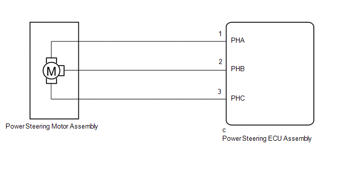
The power steering ECU assembly supplies current to the power steering motor assembly through the motor circuit.
| DTC No. | Detection Item | DTC Detection Condition | Trouble Area | Warning Indicate | Return-to-normal Condition |
|---|---|---|---|---|---|
| C1524 | Motor Terminal Voltage | Short (or open) in motor circuit or abnormal voltage or current in motor circuit |
| On | Power switch on (IG) again |
| C1555 | Motor Relay Welding Failure | Motor relay circuit malfunction |
| On | Power switch on (IG) again |
WIRING DIAGRAM
CAUTION / NOTICE / HINT
NOTICE:
If the power steering ECU assembly has been replaced, perform assist map writing.
Click here .gif)
PROCEDURE
| 1. | INSPECT TIGHTENING TORQUE OF MOTOR TERMINAL BOLT |
(a) Disengage the 4 claws to remove the protector.
Click here
(b) Check that the motor terminal bolts are tightened to the specified torque.
Click here
OK:
The motor terminal bolts are tightened to the specified torque.
| NG | .gif) | TIGHTEN BOLT TO SPECIFIED TORQUE |
|
.gif)
| 2. | INSPECT POWER STEERING MOTOR ASSEMBLY |
| (a) Remove the power steering motor assembly. Click here |
|
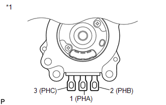
(b) Measure the resistance according to the value(s) in the table below.
Standard Resistance:
| Tester Connection | Condition | Specified Condition |
|---|---|---|
| 1 (PHA) - 2 (PHB) | 25°C (77°F) | 12.7 to 17.2 mΩ |
| 2 (PHB) - 3 (PHC) | 25°C (77°F) | 12.7 to 17.2 mΩ |
| 3 (PHC) - 1 (PHA) | 25°C (77°F) | 12.7 to 17.2 mΩ |
| 1 (PHA) - Motor case | Always | 10 kΩ or higher |
| 2 (PHB) - Motor case | Always | 10 kΩ or higher |
| 3 (PHC) - Motor case | Always | 10 kΩ or higher |
| NG | | REPLACE POWER STEERING MOTOR ASSEMBLY |
|
| 3. | READ VALUE USING TECHSTREAM (MOTOR TERMINAL VOLT) |
(a) Turn the power switch off.
(b) Connect the Techstream to the DLC3.
(c) Turn the power switch on (READY).
(d) Turn the Techstream on.
(e) Enter the following menus: Chassis / EMPS / Data List.
(f) Select the items "Motor Terminal Volt (U)", "Motor Terminal Volt (V)" and "Motor Terminal Volt (W)" in the Data List and read the value displayed on the Techstream.
Chassis > EMPS > Data List| Tester Display | Measurement Item | Range | Normal Condition | Diagnostic Note |
|---|---|---|---|---|
| Motor Terminal Volt(U) | Motor terminal voltage (A phase) | Min.: 0.000 V Max.: 98.000 V | Power switch on (READY) and steering wheel being turned: Value changes within 4 to 35 V range | - |
| Motor Terminal Volt(V) | Motor terminal voltage (B phase) | Min.: 0.000 V Max.: 98.000 V | Power switch on (READY) and steering wheel being turned: Value changes within 4 to 35 V range | - |
| Motor Terminal Volt(W) | Motor terminal voltage (C phase) | Min.: 0.000 V Max.: 98.000 V | Power switch on (READY) and steering wheel being turned: Value changes within 4 to 35 V range | - |
| Tester Display |
|---|
| Motor Terminal Volt(U) |
| Motor Terminal Volt(V) |
| Motor Terminal Volt(W) |
| Result | Proceed to |
|---|---|
| During steering operation, value changes within 4 to 35 V range. | A |
| During steering operation, voltage is not generated. | B |
| A | | REPLACE POWER STEERING ECU ASSEMBLY |
| B | | REPLACE POWER STEERING MOTOR ASSEMBLY |
READ NEXT:
 Motor Rotation Angle Sensor (C1528)
DESCRIPTION The motor rotation angle sensor detects the motor rotation angle and sends this information to the power steering ECU assembly. DTC No. Detection Item DTC Detection Condition Trou
Vehicle Speed Signal (C1541)
DESCRIPTION The power steering ECU assembly receives vehicle speed signals from the skid control ECU via CAN communication. The ECU provides appropriate assisting force in accordance with the vehicle
IG Power Supply Voltage (C1551)
DESCRIPTION The power steering ECU assembly distinguishes the power switch status as on (IG) or off through the IG power source circuit. DTC No. Detection Item DTC Detection Condition Trouble
SEE MORE:
How To Proceed With Troubleshooting
CAUTION / NOTICE / HINT HINT:
Use the following procedure to troubleshoot the automatic high beam system.
*: Use the Techstream.
PROCEDURE 1. VEHICLE BROUGHT TO WORKSHOP
NEXT 2. INSPECT AUXILIARY BATTERY VOLTAGE (a) Measure the auxiliary battery voltage wit
DC / DC Converter Performance (P0A94-550,P0E32-564)
DTC SUMMARY MALFUNCTION DESCRIPTION These DTCs indicate a malfunction inside the inverter for the motor. The cause of this malfunction may be one of the following: Internal inverter malfunction
Internal circuit malfunction in the inverter for the motor
Malfunction in the sensors for inverter co
