Lexus NX: No. 1 Clearance Warning Buzzer Circuit
DESCRIPTION
This circuit consists of the No. 1 clearance warning buzzer and clearance warning ECU assembly. An ECU-excited type buzzer is used. The ECU operates the buzzers using a sound pattern that changes depending on the distance to the obstacle.
WIRING DIAGRAM
PROCEDURE
| 1. | PERFORM ACTIVE TEST USING TECHSTREAM |
(a) Connect the Techstream to the DLC3.
(b) Turn the power switch on (IG).
(c) Turn the Techstream on.
(d) Enter the following menus: Body Electrical / Advanced Parking Guidance/ICS/Intuitive P/A / Active Test.
(e) Check that the buzzer operates by performing the Active Test.
Body Electrical > Advanced Parking Guidance/ICS/Intuitive P/A > Active Test| Tester Display | Measurement Item | Control Range | Diagnostic Note |
|---|---|---|---|
| Front Buzzer | No. 1 clearance warning buzzer | Operate or Stop | Confirm that the vehicle is stopped and the power switch is on (IG) |
| Tester Display |
|---|
| Front Buzzer |
OK:
The No. 1 clearance warning buzzer sounds.
| OK | .gif) | PROCEED TO NEXT SUSPECTED AREA SHOWN IN PROBLEM SYMPTOMS TABLE |
|
.gif)
| 2. | CHECK HARNESS AND CONNECTOR (CLEARANCE WARNING ECU ASSEMBLY - NO. 1 CLEARANCE WARNING BUZZER) |
(a) Disconnect the I20 clearance warning ECU assembly connector.
(b) Disconnect the I21 No. 1 clearance warning buzzer connector.
(c) Measure the resistance according to the value(s) in the table below.
Standard Resistance:
| Tester Connection | Condition | Specified Condition |
|---|---|---|
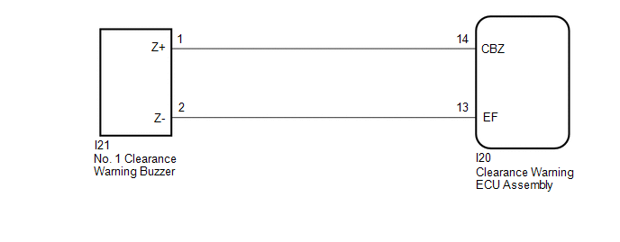
| I20-14 (CBZ) - I21-1 (Z+) | Always | Below 1 Ω |
| I20-13 (EF) - I21-2 (Z-) | Always | Below 1 Ω |
| I20-14 (CBZ) or I21-1 (Z+) - Body ground | Always | 10 kΩ or higher |
| I20-13 (EF) or I21-2 (Z-) - Body ground | Always | 10 kΩ or higher |
| NG | | REPAIR OR REPLACE HARNESS OR CONNECTOR |
|
| 3. | REPLACE NO. 1 CLEARANCE WARNING BUZZER |
(a) Replace the No. 1 clearance warning buzzer with a new or known good one.
Click here .gif)
|
| 4. | PERFORM ACTIVE TEST USING TECHSTREAM |
(a) Connect the Techstream to the DLC3.
(b) Turn the power switch on (IG).
(c) Turn the Techstream on.
(d) Enter the following menus: Body Electrical / Advanced Parking Guidance/ICS/Intuitive P/A / Active Test.
(e) Check that the buzzer operates by performing the Active Test.
Body Electrical > Advanced Parking Guidance/ICS/Intuitive P/A > Active Test| Tester Display | Measurement Item | Control Range | Diagnostic Note |
|---|---|---|---|
| Front Buzzer | No. 1 clearance warning buzzer | Operate or Stop | Confirm that the vehicle is stopped and the power switch is on (IG) |
| Tester Display |
|---|
| Front Buzzer |
OK:
The No. 1 clearance warning buzzer sounds.
| OK | | END (NO. 1 CLEARANCE WARNING BUZZER WAS DEFECTIVE) |
| NG | | REPLACE CLEARANCE WARNING ECU ASSEMBLY |
READ NEXT:
 Clearance Warning ECU Power Source Circuit
DESCRIPTION This circuit provides power to operate the clearance warning ECU assembly. WIRING DIAGRAM CAUTION / NOTICE / HINT NOTICE: Inspect the fuses for circuits related to this system before perf
No. 2 Clearance Warning Buzzer Circuit
DESCRIPTION This circuit consists of the No. 2 clearance warning buzzer and clearance warning ECU assembly. An ECU-excited type buzzer is used. The ECU operates the buzzers using a sound pattern that
Sensor Frozen Indication (Dirty or Frozen)
DESCRIPTION When the ultrasonic sensor is dirty or frozen, "Parking Assist Unavailable Clean Parking Assist Sensor" is displayed on the multi-information display in the combination meter assembly. PRO
SEE MORE:
Radio Receiver Power Source Circuit
DESCRIPTION This is the power source circuit to operate the radio receiver assembly. WIRING DIAGRAM CAUTION / NOTICE / HINT NOTICE:
Inspect the fuses for circuits related to this system before performing the following procedure.
When replacing the radio receiver assembly, always replace it wit
Power Window Master Switch
ComponentsCOMPONENTS ILLUSTRATION *1 MULTIPLEX NETWORK MASTER SWITCH ASSEMBLY *2 POWER WINDOW REGULATOR MASTER SWITCH ASSEMBLY WITH FRONT DOOR ARMREST BASE PANEL *3 FRONT DOOR ARMREST BASE PANEL - - RemovalREMOVAL PROCEDURE 1. REMOVE POWER WINDOW REGULATOR MASTER SWITCH ASSE
