Lexus NX: Power Window Master Switch
Components
COMPONENTS
ILLUSTRATION
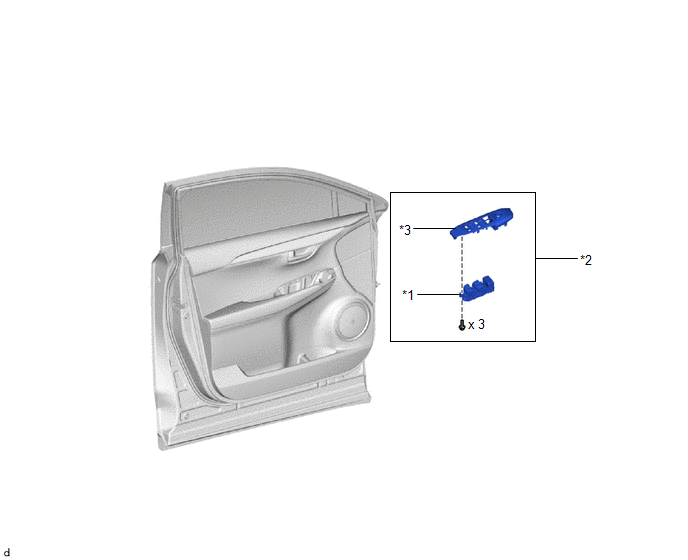
| *1 | MULTIPLEX NETWORK MASTER SWITCH ASSEMBLY | *2 | POWER WINDOW REGULATOR MASTER SWITCH ASSEMBLY WITH FRONT DOOR ARMREST BASE PANEL |
| *3 | FRONT DOOR ARMREST BASE PANEL | - | - |
Removal
REMOVAL
PROCEDURE
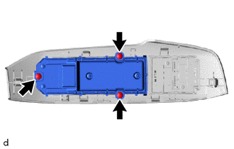
1. REMOVE POWER WINDOW REGULATOR MASTER SWITCH ASSEMBLY WITH FRONT DOOR ARMREST BASE PANEL
Click here .gif)
2. REMOVE MULTIPLEX NETWORK MASTER SWITCH ASSEMBLY
| (a) Remove the 3 screws and multiplex network master switch assembly. |
|
Inspection
INSPECTION
PROCEDURE
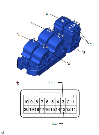
1. INSPECT MULTIPLEX NETWORK MASTER SWITCH ASSEMBLY
| (a) Check that the LED illuminates. (1) Apply auxiliary battery voltage to the multiplex network master switch assembly and check that the LED illuminates. OK:
If the result is not as specified, replace the multiplex network master switch assembly. |
|
Installation
INSTALLATION
PROCEDURE
1. INSTALL MULTIPLEX NETWORK MASTER SWITCH ASSEMBLY
(a) Install the multiplex network master switch assembly with the 3 screws.
2. INSTALL POWER WINDOW REGULATOR MASTER SWITCH ASSEMBLY WITH FRONT DOOR ARMREST BASE PANEL
Click here .gif)
READ NEXT:
 Components
COMPONENTS ILLUSTRATION *1 DECK FLOOR BOX LH *2 NO. 3 DECK BOARD SUB-ASSEMBLY *3 REAR DECK FLOOR BOX *4 NEGATIVE AUXILIARY BATTERY TERMINAL N*m (kgf*cm, ft.*lbf): Specified
Removal
REMOVAL CAUTION / NOTICE / HINT HINT:
Use the same procedure for the RH and LH sides.
The procedure listed below is for the LH side.
PROCEDURE 1. PRECAUTION NOTICE: After the power switch is t
SEE MORE:
Installation
INSTALLATION CAUTION / NOTICE / HINT CAUTION: Wear protective gloves. Sharp areas on the parts may injure your hands. HINT:
Use the same procedure for the RH and LH sides.
The procedure listed below is for the LH side.
PROCEDURE 1. INSTALL SEPARATE TYPE FRONT SEAT CUSHION COVER LH HINT:
W
Parts Location
PARTS LOCATION ILLUSTRATION *1 ENGINE ROOM RELAY BLOCK
- AM2 FUSE
*2 WIRELESS DOOR LOCK BUZZER *3 DOOR CONTROL RECEIVER - - ILLUSTRATION *A w/o Power Back Door System *B w/ Power Back Door System *1 BACK DOOR COURTESY LIGHT SWITCH ASSEMBLY *2 BACK DOO
