Lexus NX: On-vehicle Inspection
ON-VEHICLE INSPECTION
PROCEDURE
1. INSPECT WINDSHIELD WIPER SWITCH ASSEMBLY
(a) w/o Auto Wiper System:
Check the front wiper intermittent operation.
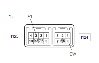
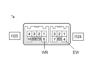
| (1) Connect a voltmeter positive (+) lead to terminal I125-3 (+1) and a negative (-) lead to terminal I124-4 (EW). |
|
(2) Turn the power switch on (IG).
(3) Turn the wiper switch to the INT position.
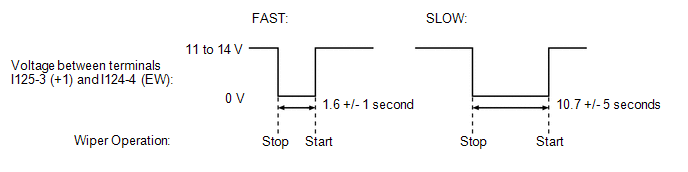
(4) Operate the intermittent wiper and check the voltage between terminals I125-3 (+1) and I124-4 (EW).
OK:
Voltage changes as shown in the illustration.
If the result is not as specified, replace the windshield wiper switch assembly.
(b) Check the front washer operation.
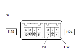
| (1) Connect a voltmeter positive (+) lead to terminal I124-7 (WF) and a negative (-) lead to terminal I124-4 (EW). |
|
(2) Turn the power switch on (IG).
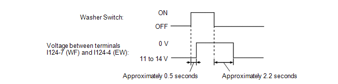
(3) Turn the washer switch on and off, and check the voltage between terminals I124-7 (WF) and I124-4 (EW).
OK:
Voltage changes as shown in the following illustration.
If the result is not as specified, replace the windshield wiper switch assembly.
(c) Check the rear washer operation.
| (1) Connect a voltmeter positive (+) lead to terminal I125-5 (WR) and a negative (-) lead to terminal I124-4 (EW). |
|
(2) Turn the power switch on (IG).
(3) Turn the washer switch on and off, and check the voltage between terminals I125-5 (WR) and I124-4 (EW).
OK:
Voltage changes as shown in the following illustration.
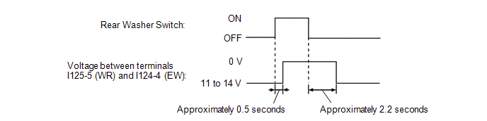
If the result is not as specified, replace the windshield wiper switch assembly.
READ NEXT:
 Removal
REMOVAL PROCEDURE 1. PRECAUTION CAUTION: Be sure to read Precoution thoroughly before serving. Click here NOTICE: After the power switch is turned off, there may be a waiting time before disconnecti
Inspection
INSPECTION PROCEDURE 1. INSPECT WINDSHIELD WIPER SWITCH ASSEMBLY (a) w/o Auto Wiper System: (1) Measure the resistance according to the value(s) in the table below. Standard Resistance: Front Wipe
Installation
INSTALLATION PROCEDURE 1. INSTALL WINDSHIELD WIPER SWITCH ASSEMBLY (a) Attach the claw to install the windshield wiper switch assembly. (b) Connect each connector. 2. INSTALL UPPER STEERING COLUMN COV
SEE MORE:
Remote Touch Screen Does not Generate Vibration Feedback
DESCRIPTION When each button displayed on the multi-display assembly is selected via remote touch screen operation, the remote touch screen generates vibration feedback according to communication between the remote touch and radio receiver assembly. CAUTION / NOTICE / HINT NOTICE: When replacing the
Vehicle Specifications have not been Stored (B2451)
DESCRIPTION This DTC is output if the vehicle variation information is not written to the headlight ECU sub-assembly LH. The headlight ECU sub-assembly LH outputs DTC B2451. DTC No. Detection Item DTC Detection Condition Trouble Area B2451 Vehicle Specifications have not been Stored
