Lexus NX: Removal
REMOVAL
PROCEDURE
1. PRECAUTION
CAUTION:
Be sure to read Precoution thoroughly before serving.
Click here .gif)
NOTICE:
After the power switch is turned off, there may be a waiting time before disconnecting the negative (-) auxiliary battery terminal.
Click here
2. REMOVE NO. 3 DECK BOARD SUB-ASSEMBLY
Click here
3. REMOVE REAR DECK FLOOR BOX
Click here
4. REMOVE DECK FLOOR BOX LH
Click here
5. DISCONNECT CABLE FROM NEGATIVE AUXILIARY BATTERY TERMINAL (for Manual Tilt and Manual Telescopic Steering Column)
Click here
CAUTION:
Wait at least 90 seconds after disconnecting the cable from the negative (-) auxiliary battery terminal to disable the SRS system.
6. DISCONNECT CABLE FROM NEGATIVE AUXILIARY BATTERY TERMINAL (for Power Tilt and Power Telescopic Steering Column)
(a) Disable the auto tilt away function by changing the customize parameter.
Click here
NOTICE:
Record the current customize parameter setting (whether the auto tilt away function is enabled or disabled) in order to restore the current setting after finishing the operation.
HINT:
Performing the above operation causes the auto tilt away function to be disabled when the power switch is turned off.
(b) Turn the power switch on (IG). Operate the tilt and telescopic switch to fully extend and lower the steering column assembly.
(c) Turn the power switch off and disconnect the cable from the auxiliary battery negative (-) terminal.
Click here
CAUTION:
Wait at least 90 seconds after disconnecting the cable from the negative (-) auxiliary battery terminal to disable the SRS system.
7. REMOVE LOWER STEERING COLUMN COVER SUB-ASSEMBLY (for Manual Tilt and Manual Telescopic Steering Column)
NOTICE:
Removing the lower steering column cover sub-assembly in the incorrect order will cause the parts to break.
(a) Release the tilt and telescopic lever, and fully extend and lower the steering column assembly.
(b) Lock the tilt and telescopic lever.
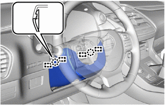
| (c) Turn the steering wheel assembly to the left and remove the screw. |
|
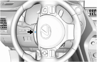
| (d) Turn the steering wheel assembly to the right and remove the screw. |
|
| (e) Insert your fingers into the opening of the tilt lever of the lower steering column cover sub-assembly to detach the claw <A>. HINT: Spread the claw to detach it. |
|
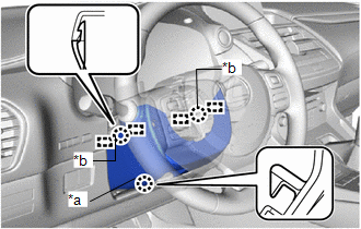
(f) Push the lower steering column cover sub-assembly to detach the 2 claws <B> and 4 guides and remove the lower steering column cover sub-assembly.
8. REMOVE LOWER STEERING COLUMN COVER SUB-ASSEMBLY (for Power Tilt and Power Telescopic Steering Column)
NOTICE:
Removing the lower steering column cover sub-assembly in the incorrect order will cause the parts to break.
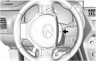
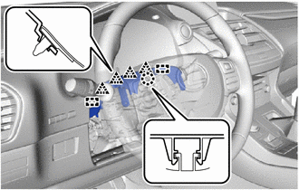
| (a) Turn the steering wheel assembly to the left and remove the screw. |
|
| (b) Turn the steering wheel assembly to the right and remove the screw. |
|
| (c) Remove the screw. |
|
| (d) Push the lower steering column cover sub-assembly to detach the 2 claws and 4 guides and remove the lower steering column cover sub-assembly. |
|
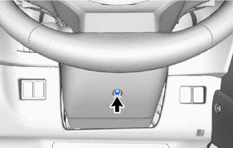
9. REMOVE UPPER STEERING COLUMN COVER
| (a) Detach the 4 clips and 2 guides to separate the instrument cluster finish panel cover from the upper steering column cover. |
|
(b) Detach the claw and remove the upper steering column cover.
10. REMOVE WINDSHIELD WIPER SWITCH ASSEMBLY
| (a) Disconnect each connector. |
|
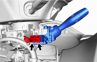
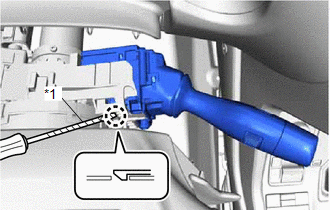
| (b) Using a screwdriver, detach the claw and remove the windshield wiper switch assembly as shown in the illustration. NOTICE: If the claw is pulled with excessive force, it may break. |
|
READ NEXT:
 Inspection
INSPECTION PROCEDURE 1. INSPECT WINDSHIELD WIPER SWITCH ASSEMBLY (a) w/o Auto Wiper System: (1) Measure the resistance according to the value(s) in the table below. Standard Resistance: Front Wipe
Installation
INSTALLATION PROCEDURE 1. INSTALL WINDSHIELD WIPER SWITCH ASSEMBLY (a) Attach the claw to install the windshield wiper switch assembly. (b) Connect each connector. 2. INSTALL UPPER STEERING COLUMN COV
SEE MORE:
Thermostat
ComponentsCOMPONENTS ILLUSTRATION *1 THERMOSTAT *2 WATER INLET *3 GASKET - - N*m (kgf*cm, ft.*lbf): Specified torque ● Non-reusable part RemovalREMOVAL PROCEDURE 1. DRAIN ENGINE COOLANT Click here 2. DISCONNECT WATER INLET (a) Remove the 2 nuts and disconne
Fail-safe Chart
FAIL-SAFE CHART ASC System (a) The stereo component equalizer assembly stores DTCs and freeze frame data and stops sound output if it detects any of the following abnormalities. Item Abnormality Detection Condition Fail-safe Control DTC Output Return Condition CAN communication malfun
