Lexus NX: Open in +B Circuit (C13AD)
DESCRIPTION
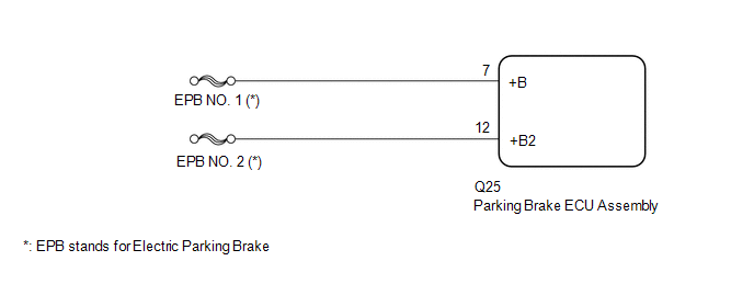
The parking brake ECU assembly is supplied with power to operate the motor via the +B and +B2 terminals.
| DTC No. | Detection Item | DTC Detection Condition | Trouble Area | Memory | Note |
|---|---|---|---|---|---|
| C13AD | Open in +B Circuit | All of following conditions are met:
HINT: *: This value is based on the assumption that the auxiliary battery voltage is 12 V. |
| Yes | An electric parking brake system malfunction is displayed on the multi-information display. |
WIRING DIAGRAM
CAUTION / NOTICE / HINT
NOTICE:
- Inspect the fuses for circuits related to this system before performing the following inspection procedure.
- Before disconnecting connectors or fuses, turn the power switch off and wait 20 seconds or more.
- When replacing the parking brake ECU assembly, operate the electric parking brake switch (integration control and panel assembly), as the parking brake indicator light (red) blinks when the power switch is first turned on (IG).
PROCEDURE
| 1. | READ VALUE USING TECHSTREAM (ECU +B1 VOLTAGE / ECU +B2 VOLTAGE) |
(a) Turn the power switch off.
(b) Connect the Techstream to the DLC3.
(c) Turn the power switch on (IG) and the Techstream on.
(d) Enter the following menus: Chassis / Electric Parking Brake / Data List.
(e) Check the Data List.
Chassis > Electric Parking Brake > Data List| Tester Display | Measurement Item | Range | Normal Condition |
|---|---|---|---|
| ECU +B1 Voltage | Parking brake ECU assembly +B voltage display | 0.00 to 20.00 V | 11 to 14 V |
| ECU +B2 Voltage | Parking brake ECU assembly +B2 voltage display | 0.00 to 20.00 V | 11 to 14 V |
| Tester Display |
|---|
| ECU +B1 Voltage |
| ECU +B2 Voltage |
| OK | .gif) | USE SIMULATION METHOD TO CHECK |
.gif)
|
.gif)
| 2. | CHECK HARNESS AND CONNECTOR (PARKING BRAKE ECU ASSEMBLY - AUXILIARY BATTERY) |
(a) Turn the power switch off.
| (b) Disconnect the parking brake ECU assembly connector. |
|
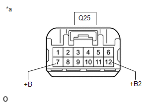
(c) Measure the voltage according to the value(s) in the table below.
Standard Voltage:
| Tester Connection | Condition | Specified Condition |
|---|---|---|
| Q25-7 (+B) - Body ground | Always | 11 to 14 V |
| Q25-12 (+B2) - Body ground | Always | 11 to 14 V |
| OK | | REPLACE PARKING BRAKE ECU ASSEMBLY |
| NG | | REPAIR OR REPLACE HARNESS OR CONNECTOR |
READ NEXT:
 System Information not Received (C13AE)
DESCRIPTION DTC No. Detection Item DTC Detection Condition Trouble Area Memory Note C13AE System Information not Received Both of following conditions are met:
Power switch is
Control Module Communication Bus OFF (U0073,U0124,U0129,U0293)
DESCRIPTION The parking brake ECU assembly communicates with the hybrid vehicle control ECU, skid control ECU (brake booster with master cylinder assembly) and deceleration sensor (airbag ECU assembly
Electric Parking Brake does not Operate
WIRING DIAGRAM CAUTION / NOTICE / HINT NOTICE:
Inspect the fuses for circuits related to this system before performing the following inspection procedure.
Before disconnecting connectors or fuse
SEE MORE:
Operation Check
OPERATION CHECK AUTOMATIC LIGHT CONTROL SYSTEM OPERATION CHECK (a) Turn the power switch on (IG). (b) Turn the headlight dimmer switch to the AUTO position. (c) Cover the automatic light control sensor. (d) Check that the taillights and low beam headlights come on. (e) Uncover the automatic light co
Inspection
INSPECTION PROCEDURE 1. INSPECT REAR CENTER ULTRASONIC SENSOR (a) Measure the resistance according to the value(s) in the table below. Standard Resistance: Tester Connection Condition Specified Condition 4 (BI) - 6 (EI) Always 10 kΩ or higher 4 (BI) - 1 (BO) Always Below
