Lexus NX: Inspection
INSPECTION
PROCEDURE
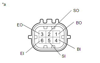
1. INSPECT REAR CENTER ULTRASONIC SENSOR
| (a) Measure the resistance according to the value(s) in the table below. Standard Resistance:
If the result is not as specified, replace the rear center ultrasonic sensor. |
|

2. INSPECT REAR CORNER ULTRASONIC SENSOR
| (a) Measure the resistance according to the value(s) in the table below. Standard Resistance:
If the result is not as specified, replace the rear corner ultrasonic sensor. |
|
READ NEXT:
 Installation
INSTALLATION PROCEDURE 1. INSTALL ULTRASONIC SENSOR CUSHION SET HINT: Perform the following procedure only when replacement of a ultrasonic sensor cushion set is necessary. (a) Install the ultrasonic
SEE MORE:
Climate Control System does not Operate on Passenger Side
DESCRIPTION The air conditioning control assembly sends operation signals to the air conditioning amplifier assembly via the LIN communication line. The air conditioning amplifier assembly actives the seat blowers according to these signals. WIRING DIAGRAM CAUTION / NOTICE / HINT NOTICE:
The cli
If the hybrid system will not start
Reasons for the hybrid system not
starting vary depending on the situation.
Check the following and perform
the appropriate procedure:
The hybrid system will not start
even though the correct starting
procedure is being followed.
One of the following may be the cause
of the problem:
Th
