Lexus NX: Speed Signal Circuit
DESCRIPTION
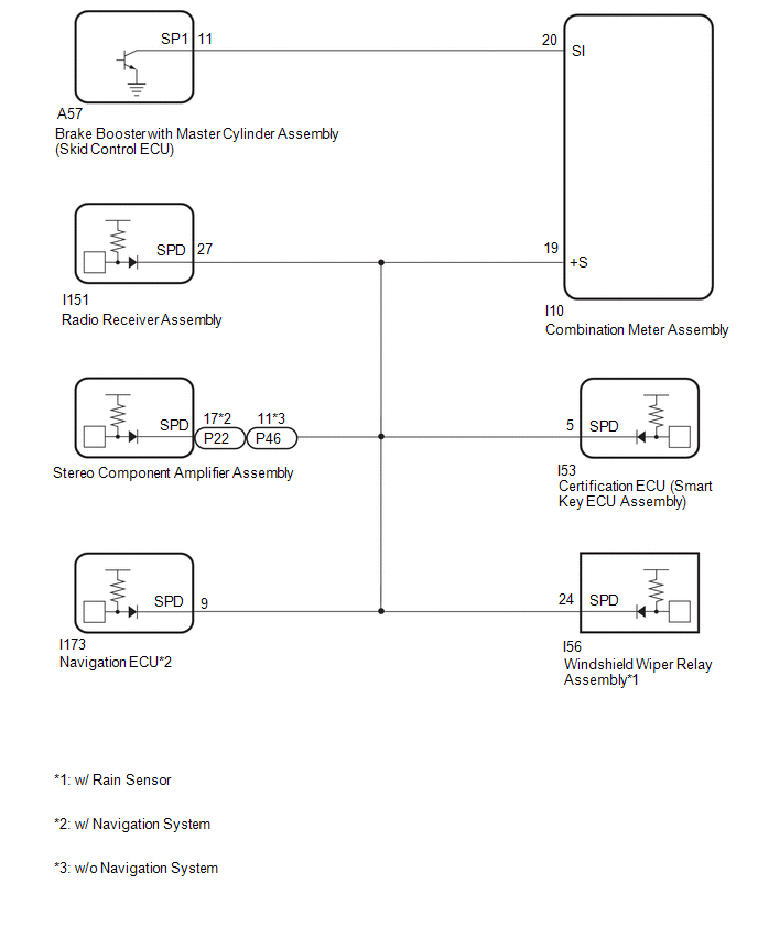
The combination meter assembly receives the vehicle speed signal from this circuit. The wheel speed sensors produce an output that varies according to the vehicle speed. The wheel speed sensor output is received by the brake booster with master cylinder assembly (skid control ECU) which uses this information to create the vehicle speed signal*. The vehicle speed signal consists of pulses sent to the combination meter assembly from the brake booster with master cylinder assembly (skid control ECU). To create this signal, 12 V is output from IG2 which is behind a resistor in the combination meter assembly. This voltage is sent to the brake booster with master cylinder assembly (skid control ECU). The pulse signal is created by switching the transistor in the brake booster with master cylinder assembly (skid control ECU) on and off, making the voltage on the wire drop to 0 V. A similar system is used for the output of this signal from the combination meter assembly via terminal +S. A voltage of 12 V or 5 V is applied to terminal +S from each ECU or relay that is connected to this terminal. The transistor in the combination meter assembly is controlled by the signal from the brake booster with master cylinder assembly (skid control ECU). When this transistor is turned on, this transistor makes the voltage supplied by the various ECUs (via their respective internal resistors) drop to 0 V. Each ECU connected to terminal +S of the combination meter assembly controls its respective system based on this pulse signal.
- *: This vehicle speed signal is created by the brake booster with master cylinder assembly (skid control ECU). There is no actual component that is referred to as the vehicle speed sensor. In addition, for some systems, vehicle speed information may be received via CAN communication.
HINT:
This circuit is used for the systems connected to terminal +S. This signal is not used for combination meter assembly operation. Combination meter assembly components such as the speedometer operate using data received via CAN communication.
WIRING DIAGRAM
CAUTION / NOTICE / HINT
NOTICE:
- When replacing the combination meter assembly, always replace it with a new one. If a combination meter assembly which was installed to another vehicle is used, the information stored in it will not match the information from the vehicle and a DTC may be stored.
- After replacing the radio receiver assembly of vehicles subscribed to pay-type satellite radio broadcasts, XM radio ID registration is necessary (w/ SXM System).
- Depending on the parts that are replaced during vehicle inspection or maintenance, performing initialization, registration or calibration may be needed.
PROCEDURE
| 1. | CHECK STEREO COMPONENT AMPLIFIER ASSEMBLY |
-
*1: w/ Rain Sensor
*2: w/ Navigation System
| (a) Disconnect the combination meter assembly connector. |
|

(b) Disconnect the I151 radio receiver assembly connector.
(c) Disconnect the I53 certification ECU (smart key ECU assembly) connector.
(d) Disconnect the I56 windshield wiper relay assembly connector.*1
(e) Disconnect the I173 navigation ECU connector.*2
(f) Measure the voltage according to the value(s) in the table below.
Standard Voltage:
| Tester Connection | Switch Condition | Specified Condition |
|---|---|---|
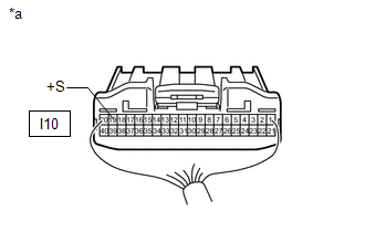
| I10-19 (+S) - Body ground | Power switch on (IG) | 4.5 to 14 V |
| Result | Proceed to |
|---|---|
| OK (w/ Navigation System) | A |
| OK (w/o Navigation System) | B |
| NG | C |
| B | .gif) | GO TO STEP 3 |
| C | | GO TO STEP 10 |
|
.gif)
| 2. | CHECK NAVIGATION ECU |
-
*1: w/ Rain Sensor
*2: w/ Navigation System
*3: w/o Navigation System
| (a) Disconnect the combination meter assembly connector. |
|
(b) Disconnect the I151 radio receiver assembly connector.
(c) Disconnect the P22*2 or P46*3 stereo component amplifier assembly connector.
(d) Disconnect the I53 certification ECU (smart key ECU assembly) connector.
(e) Disconnect the I56 windshield wiper relay assembly connector.*1
(f) Measure the voltage according to the value(s) in the table below.
Standard Voltage:
| Tester Connection | Switch Condition | Specified Condition |
|---|---|---|
| I10-19 (+S) - Body ground | Power switch on (IG) | 4.5 to 14 V |
| NG | | GO TO STEP 8 |
|
| 3. | CHECK RADIO RECEIVER ASSEMBLY |
-
*1: w/ Rain Sensor
*2: w/ Navigation System
*3: w/o Navigation System
| (a) Disconnect the combination meter assembly connector. |
|
(b) Disconnect the P22*2 or P46*3 stereo component amplifier assembly connector.
(c) Disconnect the I53 certification ECU (smart key ECU assembly) connector.
(d) Disconnect the I56 windshield wiper relay assembly connector.*1
(e) Disconnect the I173 navigation ECU connector.*2
(f) Measure the voltage according to the value(s) in the table below.
Standard Voltage:
| Tester Connection | Switch Condition | Specified Condition |
|---|---|---|
| I10-19 (+S) - Body ground | Power switch on (IG) | 4.5 to 14 V |
| NG | | GO TO STEP 11 |
|
| 4. | CHECK CERTIFICATION ECU (SMART KEY ECU ASSEMBLY) |
-
*1: w/ Rain Sensor
*2: w/ Navigation System
*3: w/o Navigation System
| (a) Disconnect the combination meter assembly connector. |
|
(b) Disconnect the I151 radio receiver assembly connector.
(c) Disconnect the P22*2 or P46*3 stereo component amplifier assembly connector.
(d) Disconnect the I56 windshield wiper relay assembly connector.*1
(e) Disconnect the I173 navigation ECU connector.*2
(f) Measure the voltage according to the value(s) in the table below.
Standard Voltage:
| Tester Connection | Switch Condition | Specified Condition |
|---|---|---|
| I10-19 (+S) - Body ground | Power switch on (IG) | 4.5 to 14 V |
| Result | Proceed to |
|---|---|
| OK (w/ Rain Sensor) | A |
| OK (w/o Rain Sensor) | B |
| NG | C |
| B | | GO TO STEP 6 |
| C | | GO TO STEP 12 |
|
| 5. | CHECK WINDSHIELD WIPER RELAY ASSEMBLY |
-
*1: w/ Navigation System
*2: w/o Navigation System
| (a) Disconnect the combination meter assembly connector. |
|
(b) Disconnect the I151 radio receiver assembly connector.
(c) Disconnect the P22*1 or P46*2 stereo component amplifier assembly connector.
(d) Disconnect the I53 certification ECU (smart key ECU assembly) connector.
(e) Disconnect the I173 navigation ECU connector.*1
(f) Measure the voltage according to the value(s) in the table below.
Standard Voltage:
| Tester Connection | Switch Condition | Specified Condition |
|---|---|---|
| I10-19 (+S) - Body ground | Power switch on (IG) | 4.5 to 14 V |
| NG | | GO TO STEP 13 |
|
| 6. | CHECK COMBINATION METER ASSEMBLY (OUTPUT VOLTAGE) |
| (a) Disconnect the brake booster with master cylinder assembly (skid control ECU) connector. |
|
(b) Measure the voltage according to the value(s) in the table below.
Standard Voltage:
| Tester Connection | Switch Condition | Specified Condition |
|---|---|---|
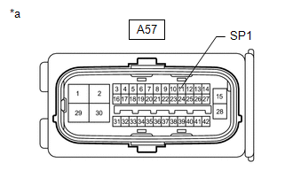
| A57-11 (SP1) - Body ground | Power switch on (IG) | 11 to 14 V |
| NG | | GO TO STEP 9 |
|
| 7. | CHECK COMBINATION METER ASSEMBLY (INPUT WAVEFORM) |
| (a) Remove the combination meter assembly with the connector(s) still connected. |
|
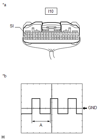
(b) Connect an oscilloscope to terminal I10-20 (SI) and body ground.
(c) Check the signal waveform according to the condition(s) in the table below.
Measurement Condition| Item | Condition |
|---|---|
| Tester Connection | I10-20 (SI) - Body ground |
| Tool Setting | 5 V/DIV., 20 ms./DIV. |
| Vehicle Condition | Driving at approximately 20 km/h (12 mph) |
HINT:
When the system is functioning normally, one wheel revolution generates 4 pulses. As the vehicle speed increases, the width indicated by A in the illustration narrows.
OK:
The waveform displayed is as shown in the illustration.
| OK | | REPLACE COMBINATION METER ASSEMBLY |
| NG | | REPLACE BRAKE BOOSTER WITH MASTER CYLINDER ASSEMBLY |
| 8. | CHECK HARNESS AND CONNECTOR (COMBINATION METER ASSEMBLY - NAVIGATION ECU) |
-
*1: w/ Rain Sensor
*2: w/ Navigation System
*3: w/o Navigation System
(a) Disconnect the I10 combination meter assembly connector.
(b) Disconnect the I151 radio receiver assembly connector.
(c) Disconnect the P22*2 or P46*3 stereo component amplifier assembly connector.
(d) Disconnect the I53 certification ECU (smart key ECU assembly) connector.
(e) Disconnect the I56 windshield wiper relay assembly connector.*1
(f) Disconnect the I173 navigation ECU connector.*2
(g) Measure the resistance according to the value(s) in the table below.
Standard Resistance:
| Tester Connection | Condition | Specified Condition |
|---|---|---|
| I10-19 (+S) - I173-9 (SPD) | Always | Below 1 Ω |
| I10-19 (+S) or I173-9 (SPD) - Body ground | Always | 10 kΩ or higher |
| OK | | REPLACE NAVIGATION ECU |
| NG | | REPAIR OR REPLACE HARNESS OR CONNECTOR |
| 9. | CHECK HARNESS AND CONNECTOR (COMBINATION METER ASSEMBLY - BRAKE BOOSTER WITH MASTER CYLINDER ASSEMBLY [SKID CONTROL ECU]) |
(a) Disconnect the I10 combination meter assembly connector.
(b) Disconnect the A57 brake booster with master cylinder assembly (skid control ECU) connector.
(c) Measure the resistance according to the value(s) in the table below.
Standard Resistance:
| Tester Connection | Condition | Specified Condition |
|---|---|---|
| I10-20 (SI) - A57-11 (SP1) | Always | Below 1 Ω |
| I10-20 (SI) or A57-11 (SP1) - Body ground | Always | 10 kΩ or higher |
| OK | | REPLACE COMBINATION METER ASSEMBLY |
| NG | | REPAIR OR REPLACE HARNESS OR CONNECTOR |
| 10. | CHECK HARNESS AND CONNECTOR (COMBINATION METER ASSEMBLY - STEREO COMPONENT AMPLIFIER ASSEMBLY) |
-
*1: w/ Rain Sensor
*2: w/ Navigation System
*3: w/o Navigation System
(a) Disconnect the I10 combination meter assembly connector.
(b) Disconnect the P22*2 or P46*3 stereo component amplifier assembly connector.
(c) Disconnect the I151 radio receiver assembly connector.
(d) Disconnect the I53 certification ECU (smart key ECU assembly) connector.
(e) Disconnect the I56 windshield wiper relay assembly connector.*1
(f) Disconnect the I173 navigation ECU connector.*2
(g) Measure the resistance according to the value(s) in the table below.
Standard Resistance:
w/ Navigation System
| Tester Connection | Condition | Specified Condition |
|---|---|---|
| I10-19 (+S) - P22-17 (SPD) | Always | Below 1 Ω |
| I10-19 (+S) or P22-17 (SPD) - Body ground | Always | 10 kΩ or higher |
w/o Navigation System
| Tester Connection | Condition | Specified Condition |
|---|---|---|
| I10-19 (+S) - P46-11 (SPD) | Always | Below 1 Ω |
| I10-19 (+S) or P46-11 (SPD) - Body ground | Always | 10 kΩ or higher |
| OK | | REPLACE STEREO COMPONENT AMPLIFIER ASSEMBLY |
| NG | | REPAIR OR REPLACE HARNESS OR CONNECTOR |
| 11. | CHECK HARNESS AND CONNECTOR (COMBINATION METER ASSEMBLY - RADIO RECEIVER ASSEMBLY) |
-
*1: w/ Rain Sensor
*2: w/ Navigation System
*3: w/o Navigation System
(a) Disconnect the I10 combination meter assembly connector.
(b) Disconnect the P22*2 or P46*3 stereo component amplifier assembly connector.
(c) Disconnect the I151 radio receiver assembly connector.
(d) Disconnect the I53 certification ECU (smart key ECU assembly) connector.
(e) Disconnect the I56 windshield wiper relay assembly connector.*1
(f) Disconnect the I173 navigation ECU connector.*2
(g) Measure the resistance according to the value(s) in the table below.
Standard Resistance:
| Tester Connection | Condition | Specified Condition |
|---|---|---|
| I10-19 (+S) - I151-27 (SPD) | Always | Below 1 Ω |
| I10-19 (+S) or I151-27 (SPD) - Body ground | Always | 10 kΩ or higher |
| OK | | REPLACE RADIO RECEIVER ASSEMBLY |
| NG | | REPAIR OR REPLACE HARNESS OR CONNECTOR |
| 12. | CHECK HARNESS AND CONNECTOR (COMBINATION METER ASSEMBLY - CERTIFICATION ECU [SMART KEY ECU ASSEMBLY]) |
-
*1: w/ Rain Sensor
*2: w/ Navigation System
*3: w/o Navigation System
(a) Disconnect the I10 combination meter assembly connector.
(b) Disconnect the P22*2 or P46*3 stereo component amplifier assembly connector.
(c) Disconnect the I151 radio receiver assembly connector.
(d) Disconnect the I53 certification ECU (smart key ECU assembly) connector.
(e) Disconnect the I56 windshield wiper relay assembly connector.*1
(f) Disconnect the I173 navigation ECU connector.*2
(g) Measure the resistance according to the value(s) in the table below.
Standard Resistance:
| Tester Connection | Condition | Specified Condition |
|---|---|---|
| I10-19 (+S) - I53-5 (SPD) | Always | Below 1 Ω |
| I10-19 (+S) or I53-5 (SPD) - Body ground | Always | 10 kΩ or higher |
| OK | | REPLACE CERTIFICATION ECU (SMART KEY ECU ASSEMBLY) |
| NG | | REPAIR OR REPLACE HARNESS OR CONNECTOR |
| 13. | CHECK HARNESS AND CONNECTOR (COMBINATION METER ASSEMBLY - WINDSHIELD WIPER RELAY ASSEMBLY) |
-
*1: w/ Rain Sensor
*2: w/ Navigation System
*3: w/o Navigation System
(a) Disconnect the I10 combination meter assembly connector.
(b) Disconnect the P22*2 or P46*3 stereo component amplifier assembly connector.
(c) Disconnect the I151 radio receiver assembly connector.
(d) Disconnect the I53 certification ECU (smart key ECU assembly) connector.
(e) Disconnect the I56 windshield wiper relay assembly connector.*1
(f) Disconnect the I173 navigation ECU connector.*2
(g) Measure the resistance according to the value(s) in the table below.
Standard Resistance:
| Tester Connection | Condition | Specified Condition |
|---|---|---|
| I10-19 (+S) - I56-24 (SPD) | Always | Below 1 Ω |
| I10-19 (+S) or I56-24 (SPD) - Body ground | Always | 10 kΩ or higher |
| OK | | REPLACE WINDSHIELD WIPER RELAY ASSEMBLY |
| NG | | REPAIR OR REPLACE HARNESS OR CONNECTOR |
READ NEXT:
 Components
COMPONENTS ILLUSTRATION *1 INSTRUMENT SIDE PANEL LH *2 NO. 1 INSTRUMENT PANEL SAFETY PAD SUB-ASSEMBLY *3 TRIP SWITCH - -
Removal
REMOVAL PROCEDURE 1. REMOVE INSTRUMENT SIDE PANEL LH Click here 2. REMOVE NO. 1 INSTRUMENT PANEL SAFETY PAD SUB-ASSEMBLY Click here 3. REMOVE TRIP SWITCH (a) Using a screwdriver, detach the
SEE MORE:
Drive Start Control System
DESCRIPTION The drive start control is controlled by the hybrid vehicle control ECU. If the hybrid vehicle control ECU determines that the shift lever and accelerator pedal are operated abnormally, driving torque is restricted and, when necessary, a warning is displayed on the combination meter asse
Parts Location
PARTS LOCATION ILLUSTRATION *1 FRONT SEAT INNER BELT ASSEMBLY LH *2 FRONT SEAT OUTER BELT ASSEMBLY LH *3 OUTER MIRROR CONTROL ECU ASSEMBLY (for Driver Side) *4 NO. 2 ENGINE ROOM RELAY BLOCK
- MIRROR FUSE
- ECU-B NO.1 FUSE
ILLUSTRATION *1 SEAT MEMORY SWITCH *2
