Lexus NX: Operation Check
OPERATION CHECK
INPUT SIGNAL CHECK
(a) Connect the Techstream to the DLC3.
(b) Check the cruise control main switch using the Data List function of the Techstream (ON-OFF, -SET, +RES and CANCEL).
.png)
| *a | +RES |
| *b | -SET |
| *c | ON-OFF |
| *d | CANCEL |
Click here .gif)
INSPECT CRUISE CONTROL MAIN SWITCH (ON-OFF)
(a) Turn the power switch on (IG).
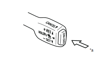
| *a | ON-OFF |
(b) Turn the dynamic radar cruise control system on using the cruise control main switch (ON-OFF).
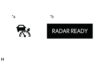
| *a | Cruise Control Indicator (Vehicle-to-vehicle Distance Control Mode) |
| *b | Multi-information Display |
(c) Check that the cruise control indicator (vehicle-to-vehicle distance control mode) in the combination meter assembly illuminates and "RADAR READY" is displayed on the multi-information display.
(d) Turn the dynamic radar cruise control system off using the cruise control main switch (ON-OFF). Check that the cruise control indicator (vehicle-to-vehicle distance control mode) in the combination meter assembly and "RADAR READY" on the multi-information display turn off.
(e) Turn the power switch off with the cruise control indicator (vehicle-to-vehicle distance control mode) in the combination meter assembly illuminated and "RADAR READY" on the multi-information display displayed. Turn the power switch back on (IG) and check the cruise control indicator (vehicle-to-vehicle distance control mode) in the combination meter assembly and "RADAR READY" on the multi-information display are turned off.
INSPECT MODE SELECT
(a) Turn the power switch on (IG).
(b) Push and hold the cruise control main switch (ON-OFF) for approximately 1.5 seconds. Check that the cruise control indicator (vehicle-to-vehicle distance control mode) in the combination meter assembly and "RADAR READY" on the multi-information display turn off and the cruise control indicator (constant speed control mode) illuminates.

| *a | ON-OFF |
(c) Check that the cruise control indicator (vehicle-to-vehicle distance control mode) in the combination meter assembly and "RADAR READY" on the multi-information display turn off and the cruise control indicator (constant speed control mode) illuminates.
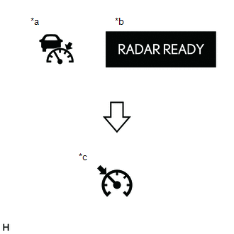
| *a | Cruise Control Indicator (Vehicle-to-vehicle Distance Control Mode) |
| *b | Multi-information Display |
| *c | Cruise Control Indicator (Constant Speed Control Mode) |
NOTICE:
Do not push any other switches before pushing the cruise control main switch to MODE. If any other switch is pushed, turn the dynamic radar cruise control system off and repeat the procedure above.
HINT:
If a malfunction is detected, turn the power switch off and repeat the procedure above.
INSPECT VEHICLE-TO-VEHICLE DISTANCE CONTROL SWITCH
(a) Turn the power switch on (IG).
(b) Turn the dynamic radar cruise control system on using the cruise control main switch (ON-OFF).

| *a | ON-OFF |
HINT:
When in constant speed control mode, the vehicle-to-vehicle distance cannot be changed.
(c) Press the vehicle-to-vehicle distance control switch.
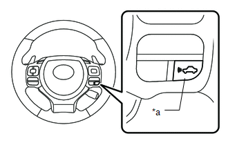
| *a | Vehicle-to-vehicle Distance Control Switch |
(d) Check that the indicator of the vehicle-to-vehicle distance, which is shown on the multi-information display in the combination meter assembly changes from long to middle to short in that order.
HINT:
Long is automatically selected each time the power switch is turned on (IG).
READ NEXT:
 Customize Parameters
CUSTOMIZE PARAMETERS CUSTOMIZE DYNAMIC RADAR CRUISE CONTROL SYSTEM (w/ Dynamic Radar Cruise Control with Road Sign Assist Function) HINT: The following items can be customized. NOTICE:
When the cus
Problem Symptoms Table
PROBLEM SYMPTOMS TABLE NOTICE:
Before replacing the hybrid vehicle control ECU, refer to Registration.
Click here
When replacing the millimeter wave radar sensor assembly, always replace it wit
Diagnosis System
DIAGNOSIS SYSTEM DIAGNOSIS FUNCTION (a) When a malfunction occurs in the dynamic radar cruise control system, the system turns off the cruise control indicator. At the same time, a short buzzer sounds
SEE MORE:
AUTO Power Retract Mirrors do not operate
DESCRIPTION When the outer mirror switch assembly is set to AUTO (neutral position), an AUTO signal is detected by the main body ECU (multiplex network body ECU). When locking and unlocking all doors with the power switch off, the main body ECU (multiplex network body ECU) sends deploy/retract signa
Components
COMPONENTS ILLUSTRATION *1 INSTRUMENT SIDE PANEL LH *2 NO. 1 INSTRUMENT PANEL SAFETY PAD SUB-ASSEMBLY *3 TRIP SWITCH - -
