- Less than approximately 15 km/h (9 mph) if speed is increasing
- Less than approximately 10 km/h (6 mph) if speed is decreasing
Lexus NX: Operation Check
OPERATION CHECK
INITIAL CHECK
(a) Power switch on (IG) (intuitive parking assist system off).
(b) Intuitive parking assist system on and check an indication state of the vehicle mark.
OK:
The initial check is performed for approximately 5 seconds after the system turns on, and then the system switches to detection operation mode.
HINT:
- During the initial check, only malfunction detection is performed. Obstacle detection is not performed.
- A frozen indication is displayed if the ultrasonic sensor is frozen.
- If an open circuit occurs in an ultrasonic sensor circuit or a malfunction is detected in a sensor (ultrasonic sensor), an open circuit indication is displayed.
MALFUNCTION DISPLAY (MULTI-INFORMATION DISPLAY)
(a) Open circuit indication
(1) If there is an open circuit between the ultrasonic sensor and the clearance warning ECU assembly or a sensor is malfunctioning, the malfunction is displayed as shown in the illustration.
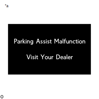
| *a | Open circuit indication |
(b) Frozen indication
(1) If a sensor is covered with foreign matter, such as mud or snow, the affected sensor is displayed as shown in the illustration.
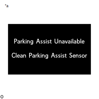
| *a | Frozen indication |
HINT:
If a frozen indication is displayed, proceed to "Sensor Frozen Indication (Dirty or Frozen)".
Click here .gif)
(c) Communication malfunction indication
(1) When a CAN communication malfunction occurs between the hybrid vehicle control ECU, combination meter assembly, and clearance warning ECU assembly, they are displayed in the same way as shown in the illustration
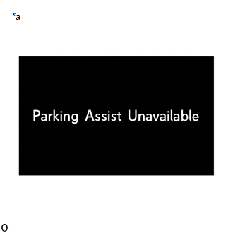
| *a | Communication malfunction indication |
DETECTION RANGE MEASUREMENT AND DISPLAY INSPECTION
NOTICE:
The following measurement and inspection will be performed with the shift lever in a position other than P. Be sure to apply the parking lever and depress the brake pedal firmly to prevent the vehicle from moving.
(a) Turn the power switch on (IG).
(b) Turn the intuitive parking assist system on.
(c) Detection range measurement:
(1) Move the shift lever according to the table below.
| Measurement Area | Shift Lever Position |
| Front Corner Sensor (front corner ultrasonic sensor) | In any position other than P |
| Front Center Sensor (front center ultrasonic sensor) | In any position other than P or R |
| Rear Corner Sensor (rear corner ultrasonic sensor) | R |
| Rear Center Sensor (rear center ultrasonic sensor) |
(2) Move a 60 mm (2.4 in.) diameter pole near each sensor to measure its detection range. When measuring the Longest-range detection of the front center sensor and the rear center sensor, use a wall or equivalent.
NOTICE:
These detection ranges are applicable when positioning the 60 mm (2.4 in.) diameter pole parallel or perpendicular to the ground. The detection range varies depending on the measuring method and type of obstacle (such as walls).
HINT:
Have an assistant move the pole.
Front Corner Sensor and Rear Corner Sensor Detection Range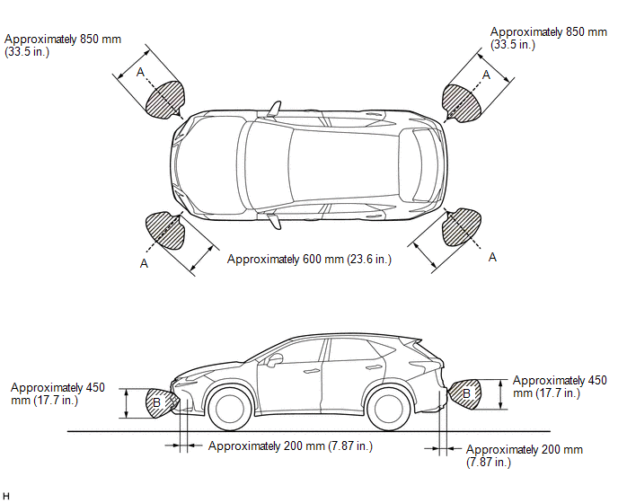
NOTICE:
The front corner sensor and rear corner sensor side view detection range (hatched area labeled (B)) represents the cross section of the top view detection range (A). The hatched area (B) does not represent the entire side view detection range.
Front Center Sensor Detection Range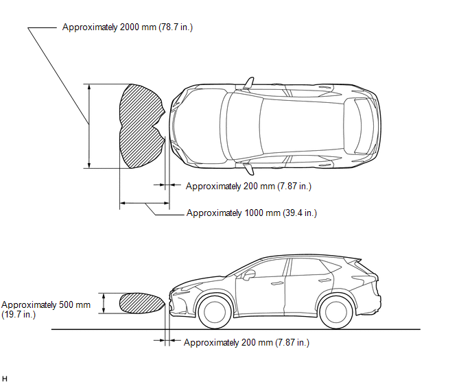 Rear Center Sensor Detection Range
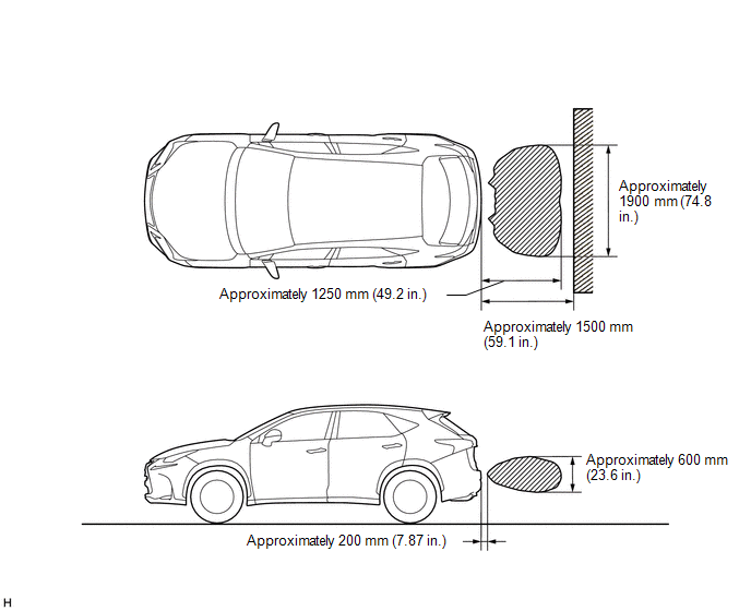
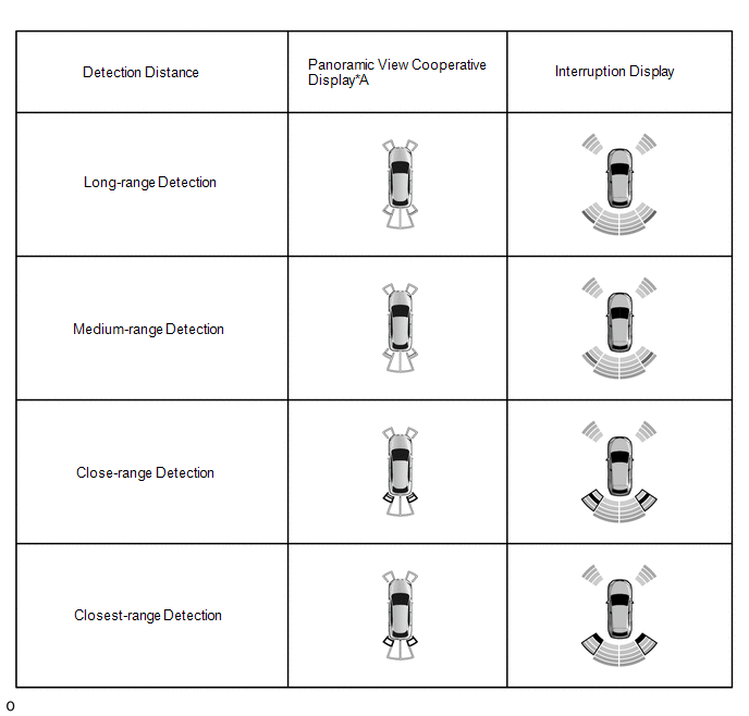
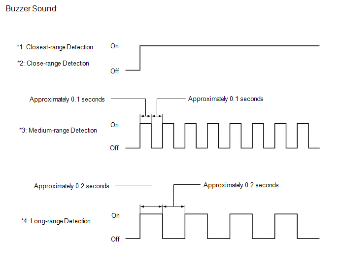
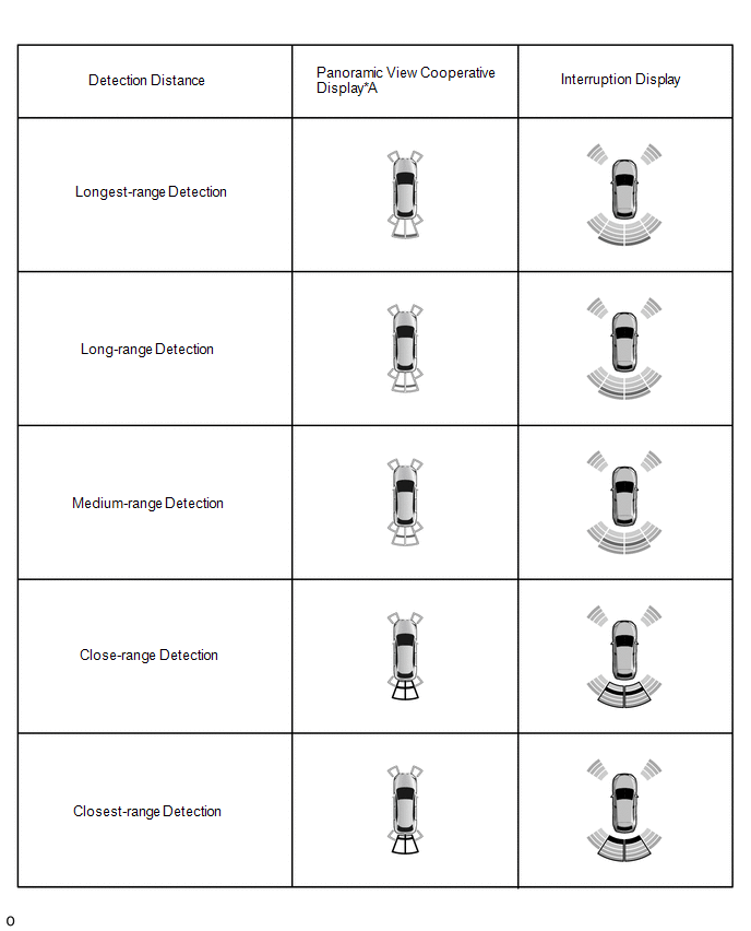
(d) Front corner sensor display and buzzer operation check
(1) When the front corner ultrasonic sensor (front corner sensor) have detected an obstacle, check the displays and check that the buzzer sounds.
Operation Condition| Power switch | Intuitive parking assist system | Shift Lever Position | Vehicle Speed* |
|---|---|---|---|
| *: When the shift position is R, the system operates at any vehicle speed. | |||
| On (IG) | On | In any position other than P | |
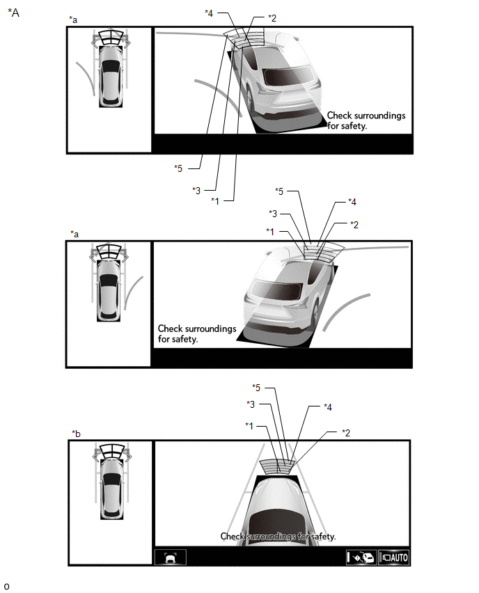
| *A | w/ Panoramic View Monitor System | - | - |
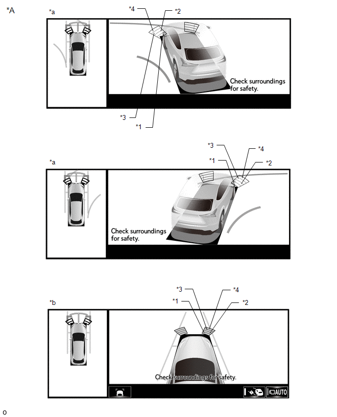
| *A | Example | - | - |
| *a | Panoramic View and Cornering View Display | *b | Panoramic View and Side Clearance View Display |
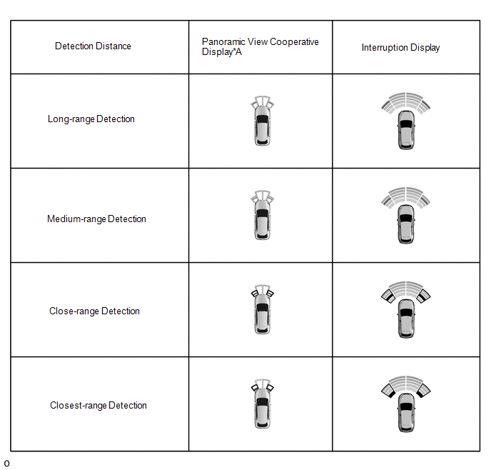
| *1 | Closest-range | *2 | Close-range |
| *3 | Medium-range | *4 | Long-range |
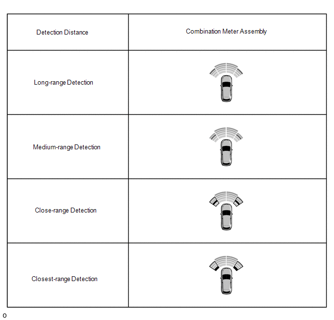
Standard:
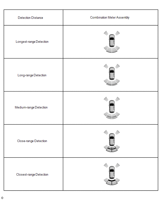
Combination Meter Assembly, Multi-display Assembly and Buzzer| Detection Range | During Judgment | Obstacle |
|---|---|---|
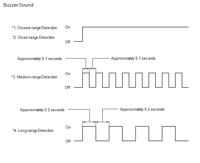
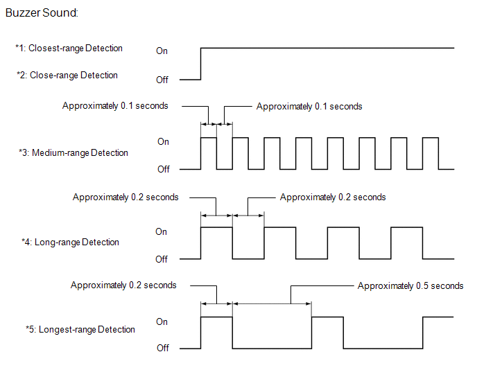
| *1: Closest-range detection Approximately 150 +/- 40 mm (5.91 +/- 1.57 in.) or less | Buzzer: Sounds continuously Color of bars displayed: Red (blinking) | 60 mm (2.4 in.) diameter pole |
| *2: Close-range detection Approximately 300 +/- 40 to 150 +/- 40 mm (11.8 +/-1.57 to 5.91 +/- 1.57 in.) | Buzzer: Sounds continuously Color of bars displayed: Red (blinking) | 60 mm (2.4 in.) diameter pole |
| *3: Medium-range detection Approximately 450 +/- 50 to 300 +/- 40 mm (17.7 +/- 1.97 to 11.8 +/- 1.57 in.) | Buzzer: Sounds intermittently (ON: 0.1 seconds / OFF: 0.1 seconds) Color of bars displayed: Yellow (Illuminated) | 60 mm (2.4 in.) diameter pole |
| *4: Long-range detection Approximately 650 +/- 60 to 450 +/- 50 mm (25.6 +/- 2.36 to 17.7 +/- 1.97 in.) | Buzzer: Sounds intermittently (ON: 0.2 seconds / OFF: 0.2 seconds) Color of bars displayed: Yellow (Illuminated) | 60 mm (2.4 in.) diameter pole |
HINT:
Ultrasonic waves are used to measure the detection range; however, the detection range may vary depending on the ambient temperature.
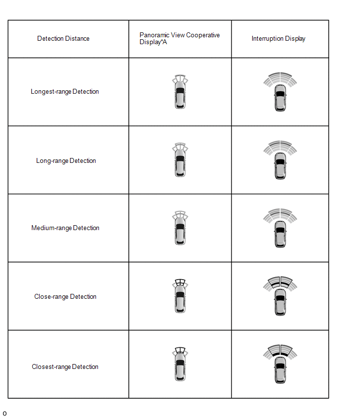
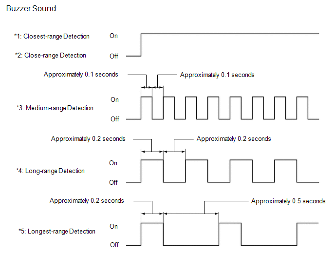
(e) Front center sensor display and buzzer operation check
(1) When the front center ultrasonic sensors (front center sensor) has detected an obstacle, check the display and check that the buzzer sounds.
Operation Condition| Power switch | Intuitive Parking Assist System | Shift Lever Position | Vehicle Speed |
|---|---|---|---|
| On (IG) | On | In any position other than P or R |
|
| *A | w/ Panoramic View Monitor System | - | - |
| *A | Example | - | - |
| *a | Panoramic View and Cornering View Display | *b | Panoramic View and Side Clearance View Display |
| *1 | Closest-range | *2 | Close-range |
| *3 | Medium-range | *4 | Long-range |
| *5 | Longest-range | - | - |
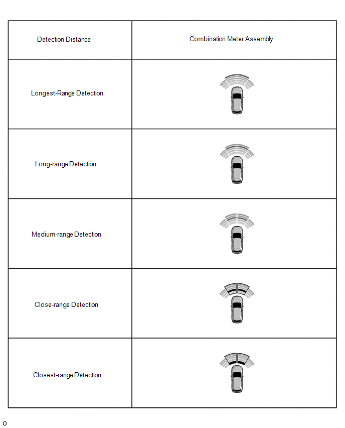
Standard:
Multi-display, Combination Meter Assembly and Buzzer| Detection Range | During Judgment | Obstacle |
|---|---|---|
| *1: Closest-range detection Approximately 150 +/- 40 mm (5.91 +/- 1.57 in.) or less | Buzzer: Sounds continuously Color of bars displayed: Red (blinking) | 60 mm (2.4 in.) diameter pole |
| *2: Close-range detection Approximately 300 +/- 40 to 150 +/- 40 mm (11.8 +/-1.57 to 5.91 +/- 1.57 in.) | Buzzer: Sounds continuously Color of bars displayed: Red (blinking) | 60 mm (2.4 in.) diameter pole |
| *3: Medium-range detection Approximately 450 +/- 50 to 300 +/- 40 mm (17.7 +/- 1.97 to 11.8 +/- 1.57 in.) | Buzzer: Sounds intermittently (ON: 0.1 seconds / OFF: 0.1 seconds) Color of bars displayed: Yellow (Illuminated) | 60 mm (2.4 in.) diameter pole |
| *4: Long-range detection Approximately 650 +/- 60 to 450 +/- 50 mm (25.6 +/- 2.36 to 17.7 +/- 1.97 in.) | Buzzer: Sounds intermittently (ON: 0.2 seconds / OFF: 0.2 seconds) Color of bars displayed: Yellow (Illuminated) | 60 mm (2.4 in.) diameter pole |
| *5: Longest-range detection Approximately 1000 +/- 110 to 650 +/- 60 mm (39.4 +/- 4.33 to 25.6 +/- 2.36 in.) | Buzzer: Sounds intermittently (ON: 0.2 seconds / OFF: 0.5 seconds) Color of bars displayed: Yellow (Illuminated) | Wall |
HINT:
Ultrasonic waves are used to measure the detection range; however, the detection range may vary depending on the ambient temperature.
(f) Rear corner sensor display and buzzer operation check
(1) When the rear corner ultrasonic sensor (rear corner sensor) has detected an obstacle, check the display and check that the buzzer sounds.
Operation Condition| Power switch | Intuitive Parking Assist System | Shift Lever Position | Vehicle Speed |
|---|---|---|---|
| On (IG) | On | R | - |
| *A | w/ Panoramic View Monitor System | - | - |
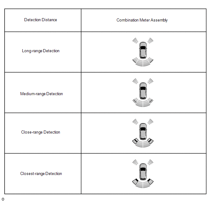
Standard:
Multi-display, Combination Meter Assembly and Buzzer| Detection Range | During Judgment | Obstacle |
|---|---|---|
| *1: Closest-range detection Approximately 150 +/- 40 mm (5.91 +/- 1.57 in.) or less | Buzzer: Sounds continuously Color of bars displayed: Red (blinking) | 60 mm (2.4 in.) diameter pole |
| *2: Close-range detection Approximately 300 +/- 40 to 150 +/- 40 mm (11.8 +/-1.57 to 5.91 +/- 1.57 in.) | Buzzer: Sounds continuously Color of bars displayed: Red (blinking) | 60 mm (2.4 in.) diameter pole |
| *3: Medium-range detection Approximately 450 +/- 50 to 300 +/- 40 mm (17.7 +/- 1.97 to 11.8 +/- 1.57 in.) | Buzzer: Sounds intermittently (ON: 0.1 seconds / OFF: 0.1 seconds) Color of bars displayed: Yellow (Illuminated) | 60 mm (2.4 in.) diameter pole |
| *4: Long-range detection Approximately 650 +/- 60 to 450 +/- 50 mm (25.6 +/- 2.36 to 17.7 +/- 1.97 in.) | Buzzer: Sounds intermittently (ON: 0.2 seconds / OFF: 0.2 seconds) Color of bars displayed: Yellow (Illuminated) | 60 mm (2.4 in.) diameter pole |
HINT:
Ultrasonic waves are used to measure the detection range; however, the detection range may vary depending on the ambient temperature.
(g) Rear center sensor display and buzzer operation check
(1) When the rear center ultrasonic sensors (rear center sensor) have detected an obstacle, check the display and check that the buzzer sounds.
Operation Condition| Power switch | Intuitive Parking Assist System | Shift Lever Position | Vehicle Speed |
|---|---|---|---|
| On (IG) | On | R | - |
| *A | w/ Panoramic View Monitor System | - | - |
Standard:
Multi-display, Combination Meter Assembly and Buzzer| Detection Range | During Judgment | Obstacle |
|---|---|---|
| *1: Closest-range detection Approximately 150 +/- 40 mm (5.91 +/- 1.57 in.) or less | Buzzer: Sounds continuously Color of bars displayed: Red (blinking) | 60 mm (2.4 in.) diameter pole |
| *2: Close-range detection Approximately 300 +/- 40 to 150 +/- 40 mm (11.8 +/-1.57 to 5.91 +/- 1.57 in.) | Buzzer: Sounds continuously Color of bars displayed: Red (blinking) | 60 mm (2.4 in.) diameter pole |
| *3: Medium-range detection Approximately 450 +/- 50 to 300 +/- 40 mm (17.7 +/- 1.97 to 11.8 +/- 1.57 in.) | Buzzer: Sounds intermittently (ON: 0.1 seconds / OFF: 0.1 seconds) Color of bars displayed: Yellow (Illuminated) | 60 mm (2.4 in.) diameter pole |
| *4: Long-range detection Approximately 650 +/- 60 to 450 +/- 50 mm (25.6 +/- 2.36 to 17.7 +/- 1.97 in.) | Buzzer: Sounds intermittently (ON: 0.2 seconds / OFF: 0.2 seconds) Color of bars displayed: Yellow (Illuminated) | 60 mm (2.4 in.) diameter pole |
| *5: Longest-range detection Approximately 1500 +/- 110 to 650 +/- 60 mm (59.1 +/- 4.33 to 25.6 +/- 2.36 in.) | Buzzer: Sounds intermittently (ON: 0.2 seconds / OFF: 0.5 seconds) Color of bars displayed: Yellow (Illuminated) | Wall |
HINT:
Ultrasonic waves are used to measure the detection range; however, the detection range may vary depending on the ambient temperature.
READ NEXT:
 Customize Parameters
CUSTOMIZE PARAMETERS CUSTOMIZE INTUITIVE PARKING ASSIST SYSTEM (a) Customizing with the Techstream. NOTICE:
When the customer requests a change in a function, first make sure that the function can
Calibration
CALIBRATION NOTICE: When any of the following parts have been replaced, perform adjustment shown in the following table. If not, the intuitive parking assist system may not operate correctly. ADJUST I
Problem Symptoms Table
PROBLEM SYMPTOMS TABLE NOTICE:
The vehicle is equipped with a Supplemental Restraint System (SRS) which includes components such as airbags. Before servicing (including removal or installation of p
SEE MORE:
Steering Lock Position Signal Circuit Malfunction (B2285)
DESCRIPTION This DTC is stored when the steering lock position signal sent by the steering lock ECU (steering lock actuator assembly) via direct line and the steering lock position signal sent via LIN communication do not match. DTC No. Detection Item DTC Detection Condition Trouble Area
Black Screen
PROCEDURE 1. CHECK DISPLAY SETTING (a) Check that the display is not in screen off mode. OK: The display setting is not in screen off mode. NG CHANGE SCREEN TO SCREEN ON MODE
OK 2. CHECK IMAGE QUALITY SETTING (a) Check that the display settings (contrast,
© 2016-2026 Copyright www.lexunx.com
