- IG Relay Monitor (Inside)
- Latch Circuit
Lexus NX: Ignition Hold Monitor Malfunction (B2271)
Lexus NX Service Manual / Vehicle Interior / Theft Deterrent / Keyless Entry / Smart Access System With Push-button Start (for Start Function) / Ignition Hold Monitor Malfunction (B2271)
DESCRIPTION
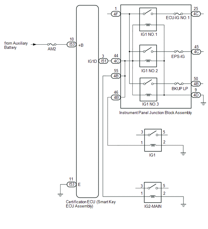
This DTC is stored when a malfunction in the IG circuit and IG hold circuit in the certification ECU (smart key ECU assembly) is detected.
| DTC No. | Detection Item | DTC Detection Condition | Trouble Area | Note |
|---|---|---|---|---|
| B2271 | Ignition Hold Monitor Malfunction | When either of the following conditions is met (1-trip detection logic*1):
|
|
|
- *1: Only detected while a malfunction is present and the power switch is on (IG).
- *2: The IG circuits activate the IG relay.
- *3: After the IG circuit turns on, even if the certification ECU (smart key ECU assembly) malfunctions, the IG hold circuit maintains the power source mode in on (IG).
| Vehicle Condition when Malfunction Detected | Fail-safe Function when Malfunction Detected |
|---|---|
| The power switch cannot be turned on (IG) (the hybrid control system cannot be started). | The power source mode cannot be changed to on (IG). |
| DTC No. | Data List and Active Test |
|---|---|
| B2271 | Power Source Control |
WIRING DIAGRAM
CAUTION / NOTICE / HINT
NOTICE:
- When using the Techstream with the power switch off, connect the Techstream to the DLC3 and turn a courtesy light switch on and off at intervals of 1.5 seconds or less until communication between the Techstream and the vehicle begins. Then select the vehicle type under manual mode and enter the following menus: Body Electrical / Smart Access. While using the Techstream, periodically turn a courtesy light switch on and off at intervals of 1.5 seconds or less to maintain communication between the Techstream and the vehicle.
-
The smart access system with push-button start (for Start Function) uses the LIN communication system and CAN communication system. Inspect the communication function by following How to Proceed with Troubleshooting. Troubleshoot the smart access system with push-button start (for Start Function) after confirming that the communication systems are functioning properly.
Click here
.gif)
- Inspect the fuses of circuits related to this system before performing the following procedure.
-
Before replacing the certification ECU (smart key ECU assembly), refer to smart access system with push-button start (for Start Function) Precaution.
Click here
- After repair, confirm that no DTCs are output by performing "DTC Output Confirmation Operation".
HINT:
When the cable is disconnected and reconnected to the negative (-) auxiliary battery terminal, the power source mode returns to the state it was in before the cable was disconnected.
PROCEDURE
| 1. | CHECK HARNESS AND CONNECTOR (POWER SOURCE) |
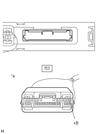
| (a) Disconnect the I53 certification ECU (smart key ECU assembly) connector. |
|
(b) Measure the voltage according to the value(s) in the table below.
Standard Voltage:
| Tester Connection | Condition | Specified Condition |
|---|---|---|
| I53-10 (+B) - Body ground | Always | 11 to 14 V |
| NG | .gif) | REPAIR OR REPLACE HARNESS OR CONNECTOR IN CIRCUIT CONNECTED TO POWER SOURCE |
|
.gif)
| 2. | CHECK HARNESS AND CONNECTOR (GROUND) |
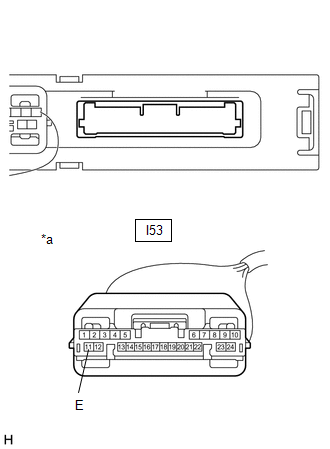
(a) Disconnect the I53 certification ECU (smart key ECU assembly) connector.
| (b) Measure the resistance according to the value(s) in the table below. Standard Resistance:
|
|
| NG | | REPAIR OR REPLACE HARNESS OR CONNECTOR |
|
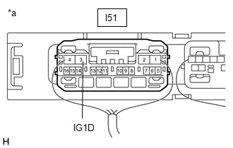
| 3. | CHECK CERTIFICATION ECU (SMART KEY ECU ASSEMBLY) |
| (a) Measure the voltage according to the value(s) in the table below. Standard Voltage:
|
|
| OK | | END (TEMPORARY CONNECTION FAILURE IS SUSPECTED) |
| NG | | REPLACE CERTIFICATION ECU (SMART KEY ECU ASSEMBLY) |
READ NEXT:
 ACC Monitor Malfunction (B2274)
DESCRIPTION This DTC is stored when a malfunction in the ACC output circuit is detected. The ACC output circuit is the circuit that goes from the ACC output terminal of the certification ECU (smart ke
STSW Monitor Malfunction (B2275)
DESCRIPTION This DTC is stored when a malfunction is detected in the starter circuit inside the certification ECU (smart key ECU assembly). DTC No. Detection Item DTC Detection Condition Trou
Detecting Vehicle Submersion (B2277)
DESCRIPTION This DTC is stored when a malfunction in the water submersion detection circuit in the certification ECU (smart key ECU assembly) is detected. DTC No. Detection Item DTC Detection C
SEE MORE:
Cruise SET Indicator Light Circuit
DESCRIPTION The hybrid vehicle control ECU illuminates the cruise SET indicator by sending request signals to the combination meter assembly via CAN communication. The cruise SET indicator illuminates when the dynamic radar cruise control system is controlling vehicle speed. If the cruise SET indica
Procedure
PROCEDURE PROCEDURE 1. CUSTOMIZE DYNAMIC RADAR CRUISE CONTROL SYSTEM Click here 2. CUSTOMIZE LANE TRACING ASSIST SYSTEM Click here 3. CUSTOMIZE ROAD SIGN ASSIST SYSTEM Click here 4. CUSTOMIZE ADAPTIVE VARIABLE SUSPENSION SYSTEM Click here 5. CUSTOMIZE POWER TILT AND POWER TELESCOPIC STEERING
© 2016-2026 Copyright www.lexunx.com
