Lexus NX: Parts Location
Lexus NX Service Manual / Vehicle Exterior / Window / Glass / Windshield Deicer System / Parts Location
PARTS LOCATION
ILLUSTRATION
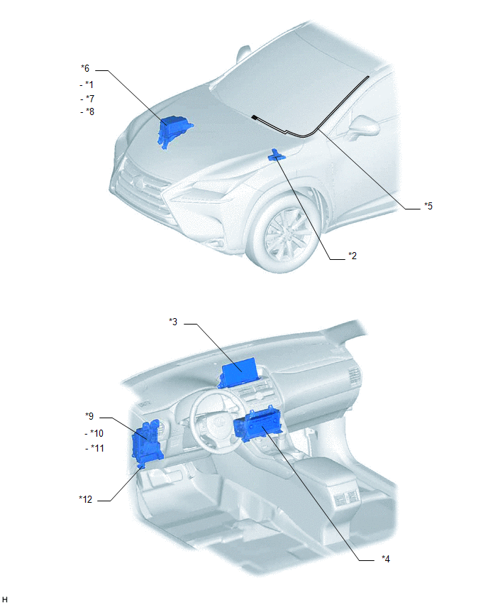
| *1 | FRONT WIPER DEICER RELAY | *2 | AIR CONDITIONING AMPLIFIER ASSEMBLY |
| *3 | MULTI-DISPLAY ASSEMBLY | *4 | RADIO RECEIVER ASSEMBLY |
| *5 | WINDSHIELD GLASS - WINDSHIELD DEICER WIRE | *6 | NO. 2 ENGINE ROOM RELAY BLOCK |
| *7 | DEICER FUSE | *8 | ECU-B NO.2 FUSE |
| *9 | INSTRUMENT PANEL JUNCTION BLOCK ASSEMBLY | *10 | ECU-IG NO.1 FUSE |
| *11 | ECU-IG NO.3 FUSE | *12 | DLC3 |
READ NEXT:
 System Diagram
SYSTEM DIAGRAM Communication Table Transmitter Receiver Signal Communication Method Multi-display Assembly Radio Receiver Assembly Windshield deicer switch signal GVIF Radio Re
System Description
SYSTEM DESCRIPTION GENERAL The windshield deicer thin heater wires are attached to the inside of the windshield glass to help deice the window surface more quickly. The indicator light illuminates whi
How To Proceed With Troubleshooting
CAUTION / NOTICE / HINT HINT:
Use the following procedure to troubleshoot the windshield deicer system.
*: Use the Techstream.
PROCEDURE 1. VEHICLE BROUGHT TO WORKSHOP
NEXT
SEE MORE:
Data List / Active Test
DATA LIST / ACTIVE TEST DATA LIST NOTICE: In the table below, the values listed under "Normal Condition" are reference values. Do not depend solely on these reference values when deciding whether a part is faulty or not. HINT: Using the Techstream to read the Data List allows the values or states of
Freeze Frame Data
FREEZE FRAME DATA FREEZE FRAME DATA (a) Whenever an automatic headlight beam level control system DTC is stored, the headlight ECU subassembly LH stores the current vehicle state as freeze frame data. CHECK FREEZE FRAME DATA (a) Connect the Techstream to the DLC3. (b) Turn the power switch on (IG).
© 2016-2026 Copyright www.lexunx.com
