- - P/SEAT F/R FUSE
Lexus NX: Parts Location
Lexus NX Service Manual / Vehicle Interior / Seat / Front Power Seat Control System(w/o Memory) / Parts Location
PARTS LOCATION
ILLUSTRATION
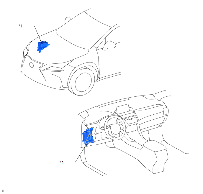
| *1 | NO. 2 ENGINE ROOM RELAY BLOCK | *2 | INSTRUMENT PANEL JUNCTION BLOCK ASSEMBLY
|
ILLUSTRATION
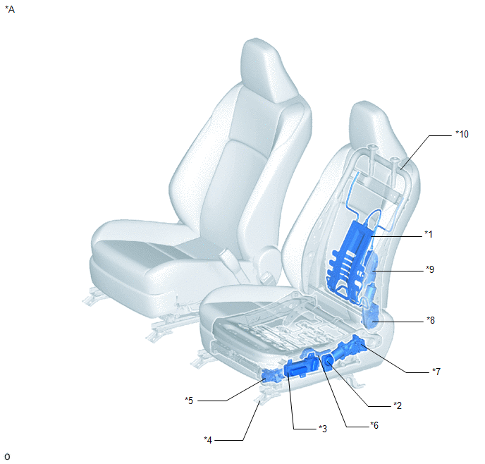
| *A | for Driver Side | - | - |
| *1 | LUMBAR SUPPORT ADJUSTER ASSEMBLY LH | *2 | FRONT LUMBAR POWER SEAT SWITCH |
| *3 | FRONT POWER SEAT SWITCH LH | *4 | FRONT SEAT ADJUSTER ASSEMBLY LH |
| *5 | SLIDE MOTOR | *6 | FRONT VERTICAL MOTOR |
| *7 | REAR LIFTER MOTOR | *8 | RECLINING MOTOR |
| *9 | LUMBAR SUPPORT MOTOR | *10 | SEPARATE TYPE FRONT SEATBACK SPRING ASSEMBLY LH |
ILLUSTRATION
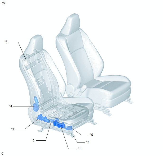
| *A | for Front Passenger Side | - | - |
| *1 | FRONT POWER SEAT SWITCH RH | *2 | FRONT VERTICAL MOTOR |
| *3 | REAR LIFTER MOTOR | *4 | RECLINING MOTOR |
| *5 | SEPARATE TYPE FRONT SEATBACK SPRING ASSEMBLY RH | *6 | SLIDE MOTOR |
| *7 | FRONT SEAT ADJUSTER ASSEMBLY RH | - | - |
READ NEXT:
 System Diagram
SYSTEM DIAGRAM
Operation Check
OPERATION CHECK CHECK POWER SEAT FUNCTION *A for Driver Side *a Slide Function *b Reclining Function *c Rear Lifter Function *d Front Vertical Function *e Lumbar Su
Problem Symptoms Table
PROBLEM SYMPTOMS TABLE HINT: Use the table below to help determine the cause of problem symptoms. If multiple suspected areas are listed, the potential causes of the symptoms are listed in order of pr
SEE MORE:
Inspection
INSPECTION PROCEDURE 1. INSPECT FRONT DOOR LOCK ASSEMBLY LH (a) Check the door lock motor operation. (1) Apply auxiliary battery voltage to the motor connector and check the operation of the door lock motor. OK: Measurement Condition Specified Condition Auxiliary battery positive (+) â†
Auto Up Operation does not Fully Close Power Window (Jam Protection Function is Activated)
DESCRIPTION If a door glass or a power window regulator motor assembly does not operate smoothly, the jam protection function may be triggered automatically, resulting in the auto up operation being unable to fully close the window. CAUTION / NOTICE / HINT NOTICE:
If a power window regulator moto
© 2016-2026 Copyright www.lexunx.com
