- - RR S-HTR RELAY (w/ Rear Seat Heater)
Lexus NX: Parts Location
PARTS LOCATION
ILLUSTRATION
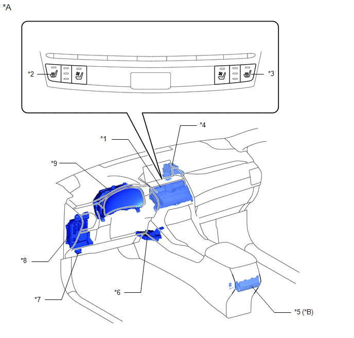
| *A | w/ Rear Seat Heater | - | - |
| *1 | AIR CONDITIONING CONTROL ASSEMBLY | *2 | SEAT HEATER SWITCH (for Driver Side) |
| *3 | SEAT HEATER SWITCH (for Front Passenger Side) | *4 | NO. 3 RELAY BLOCK |
| *5 | REFRESHING SEAT SWITCH | *6 | AIR CONDITIONING AMPLIFIER ASSEMBLY |
| *7 | DLC3 | *8 | INSTRUMENT PANEL JUNCTION BLOCK ASSEMBLY
|
| *9 | COMBINATION METER ASSEMBLY | - | - |
ILLUSTRATION
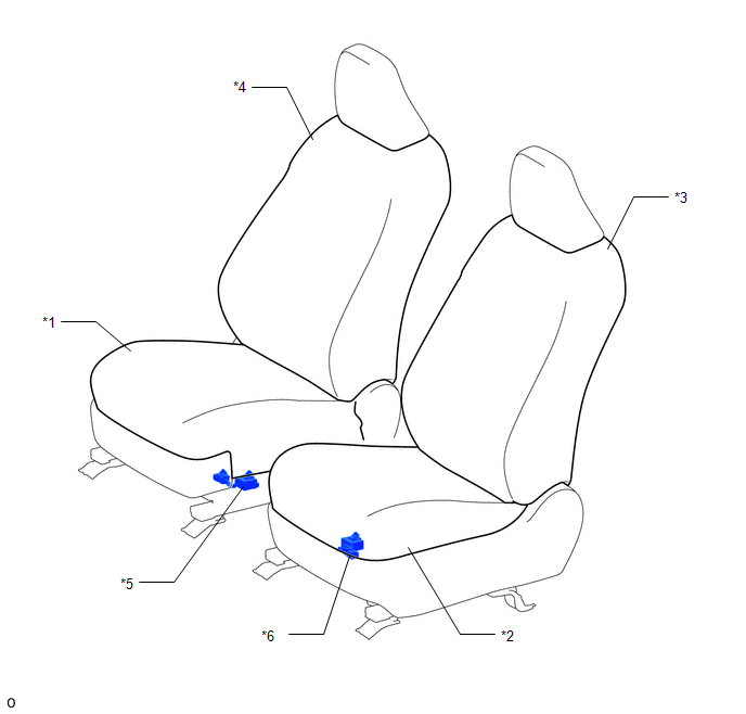
| *1 | SEPARATE TYPE FRONT SEAT CUSHION COVER RH | *2 | SEPARATE TYPE FRONT SEAT CUSHION COVER LH |
| *3 | SEPARATE TYPE FRONT SEATBACK COVER LH | *4 | SEPARATE TYPE FRONT SEATBACK COVER RH |
| *5 | SEAT HEATER CONTROL SUB-ASSEMBLY RH | *6 | SEAT HEATER CONTROL SUB-ASSEMBLY LH |
ILLUSTRATION
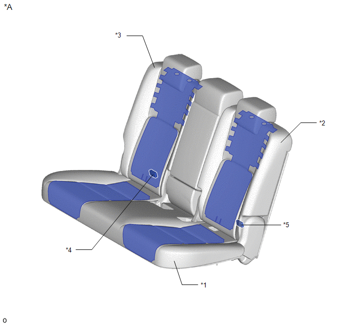
| *A | w/ Rear Seat Heater | - | - |
| *1 | BENCH TYPE REAR SEAT CUSHION COVER | *2 | SEPARATE TYPE REAR SEATBACK COVER LH |
| *3 | SEPARATE TYPE REAR SEATBACK COVER RH | *4 | SEAT HEATER CONTROL SUB-ASSEMBLY RH |
| *5 | SEAT HEATER CONTROL SUB-ASSEMBLY LH | - | - |
ILLUSTRATION
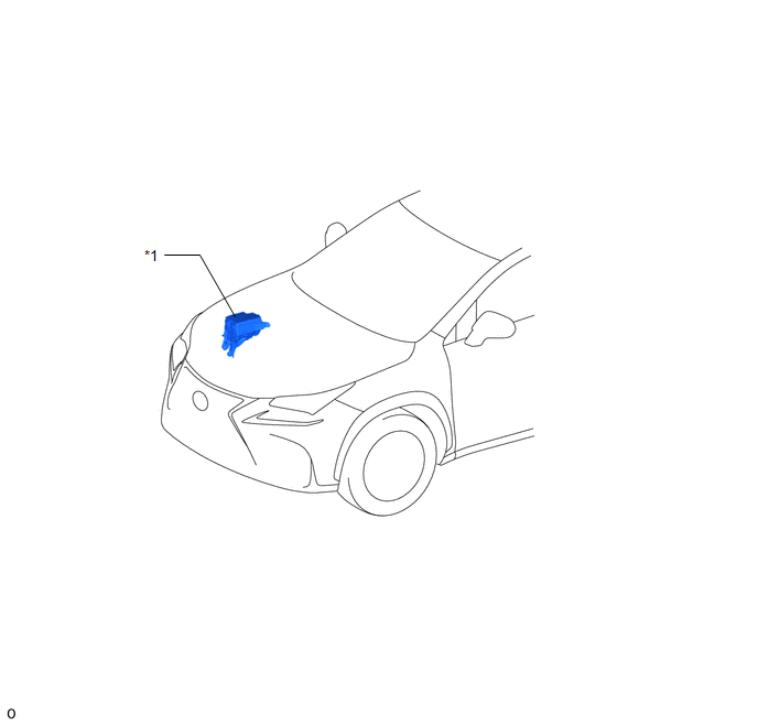
| *1 | NO. 2 ENGINE ROOM RELAY BLOCK
| - | - |
READ NEXT:
 System Diagram
SYSTEM DIAGRAM for Front: for Rear (w/ Rear Seat Heater):
System Description
SYSTEM DESCRIPTION FRONT SEAT HEATER (a) By operating the seat heater switch on the air conditioning control assembly, the temperature can be controlled within the range of 32 to 43°C (89 to 109°F).
How To Proceed With Troubleshooting
CAUTION / NOTICE / HINT HINT:
Use the following procedure to troubleshoot the seat heater system.
*: Use the Techstream.
PROCEDURE 1. VEHICLE BROUGHT TO WORKSHOP
NEXT
SEE MORE:
Disassembly
DISASSEMBLY PROCEDURE 1. REMOVE CONSOLE COMPARTMENT DOOR SUB-ASSEMBLY (a) Remove the 4 screws and console compartment door sub-assembly. 2. REMOVE NO. 3 BOX PANEL (a) Detach the 2 clips and 2 claws, 3 guides and remove the No. 3 box panel. 3. REMOVE CONSOLE BOX PLATE (a
Reassembly
REASSEMBLY PROCEDURE 1. INSTALL NUT (a) Install the 2 nuts. 2. INSTALL SYMBOL EMBLEM Click here 3. INSTALL BACK DOOR OUTSIDE GARNISH PROTECTOR (a) Clean the back door outside garnish surface. (1) Remove the double-sided tape from the back door outside garnish sub-assembly. (2) Wipe off any tape
© 2016-2026 Copyright www.lexunx.com
