Lexus NX: System Diagram
Lexus NX Service Manual / Audio & Visual & Telematics / Park Assist / Monitoring / Blind Spot Monitor System / System Diagram
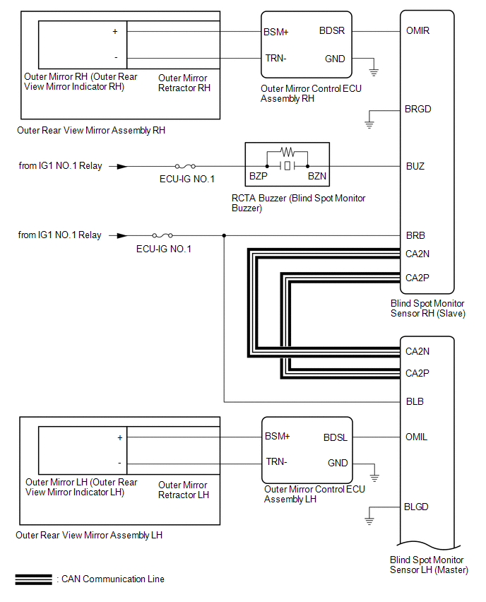
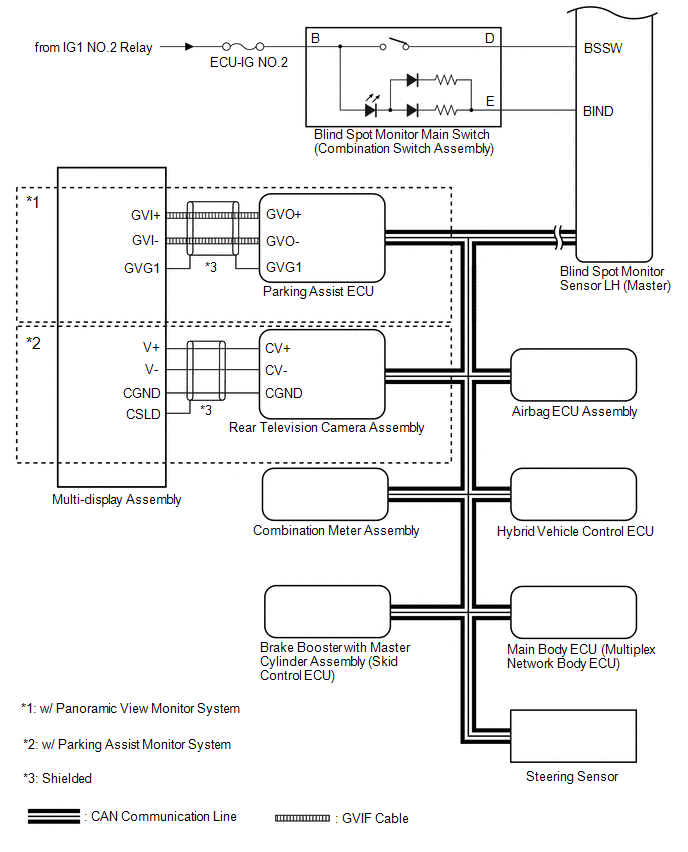
SYSTEM DIAGRAM
READ NEXT:
 System Description
SYSTEM DESCRIPTION CAN COMMUNICATION SYSTEM (a) The blind spot monitor system uses CAN communication to transmit data between the right and left blind spot monitor sensors and each ECU. (b) If there i
How To Proceed With Troubleshooting
CAUTION / NOTICE / HINT HINT:
Use the following procedure to troubleshoot the blind spot monitor system.
*: Use the Techstream.
PROCEDURE 1. VEHICLE BROUGHT TO WORKSHOP
NEXT
Operation Check
OPERATION CHECK HINT: The blind spot monitor beam axis confirmation is performed to confirm whether the sensor's beam axis is correct, and perform adjustment of the beam axis by using reflector. BLIND
SEE MORE:
Immobiliser System does not Operate Properly
DESCRIPTION The immobiliser system compares the ID code that is registered in the certification ECU (smart key ECU assembly) with the ID code of the transponder chip that is embedded in the electrical key transmitter sub-assembly. WIRING DIAGRAM Click here CAUTION / NOTICE / HINT NOTICE:
When
Ambient Temperature Sensor
ComponentsCOMPONENTS ILLUSTRATION *1 THERMISTOR ASSEMBLY (AMBIENT TEMPERATURE SENSOR) - - RemovalREMOVAL PROCEDURE 1. REMOVE FRONT BUMPER ASSEMBLY (a) for Sport Package: Click here (b) except Sport Package: Click here 2. REMOVE THERMISTOR ASSEMBLY (AMBIENT TEMPERATURE SENSOR) (
© 2016-2026 Copyright www.lexunx.com
