- Consists of a 24 GHz radar module and an integrated processing module.
- Illuminates or blinks the outer rear view mirror indicator on the outer rear view mirror assembly.
- Sounds the RCTA buzzer (blind spot monitor buzzer) when the RCTA function is operating.
- Changes the outer rear view mirror indicator on the outer rear view mirror assembly from illuminated to blinking when a turn signal switch operation signal is received from the combination meter assembly with the blind spot monitor function operating.
- Dims the outer rear view mirror indicator on the outer rear view mirror assembly and blind spot monitor indicator on the blind spot monitor main switch (combination switch assembly).
- Turns on the blind spot monitor indicator on the blind spot monitor main switch (combination switch assembly) when the blind spot monitor main switch (combination switch assembly) is on.
- Displays the RCTA icon on the multi-display assembly when the RCTA function is operating.
Lexus NX: System Description
Lexus NX Service Manual / Audio & Visual & Telematics / Park Assist / Monitoring / Blind Spot Monitor System / System Description
SYSTEM DESCRIPTION
CAN COMMUNICATION SYSTEM
(a) The blind spot monitor system uses CAN communication to transmit data between the right and left blind spot monitor sensors and each ECU.
(b) If there is a problem in the CAN communication, the right and left blind spot monitor sensors output a CAN communication malfunction DTC.
Click here .gif)
(c) Each CAN communication line has a particular length and route. Therefore, emergency repair using bypass wiring, etc. is not possible.
Click here
GENERAL
(a) The blind spot monitor system has the blind spot monitor function and RCTA function.
(1) Blind spot monitor function
- The blind spot monitor function is a function that assists the driver in making the decision to change lanes. The function uses quasi-millimeter wave radar to detect vehicles that are traveling in an adjacent lane in the area that is not reflected in the outer rear view mirror assembly. The function advises the driver of the existence of a vehicle by illuminating the outer rear view mirror indicator on the outer rear view mirror assembly.
- If the turn signal switch is operated while the outer rear view mirror indicator on an outer rear view mirror assembly is illuminated, the indicator starts blinking to give additional warning to the driver.
(2) RCTA function
- The RCTA function is a function that informs the driver of an approaching vehicle from diagonally behind. The function uses quasi-millimeter wave radar to detect the positions of and relative speed to a vehicle. When the function determines that a vehicle is approaching this vehicle, this function informs the driver of it using the indicators and buzzer.
FUNCTION OF COMPONENTS
| Component | Function |
|---|---|
|
*1: w/ Parking Assist Monitor System
*2: w/ Panoramic View Monitor System | |
| Blind Spot Monitor Sensor | |
| Outer Rear View Mirror Assembly - Outer Rear View Mirror (Outer Rear View Mirror Indicator) | Turns on or blinks the indicator based on a signal from the blind spot monitor sensor. |
| Outer Mirror Control ECU Assembly | Receives a signal from the blind spot monitor sensor and sends the signal to the outer rear view mirror indicator on the outer rear view mirror assembly. |
| Blind Spot Monitor Main Switch (Combination Switch Assembly) | Turns the blind spot monitor system on or off. |
| RCTA Buzzer (Blind Spot Monitor Buzzer) | Sounds based on a signal from the blind spot monitor sensor. |
| Combination Meter Assembly
|
|
| Main Body ECU (Multiplex Network Body ECU) | Sends the destination information and dimmer signal to the blind spot monitor sensor via CAN communication. |
| Brake Booster with Master Cylinder Assembly (Skid Control ECU) | Transmits a vehicle speed signal to the blind spot monitor sensor via CAN communication. |
| Hybrid Vehicle Control ECU | Sends a shift position signal (R) and HV flag signal to the blind spot monitor sensor via CAN communication. |
| Steering Sensor | Detects the angle of the steering wheel and sends the resulting signals to the blind spot monitor sensor via CAN communication. |
| Airbag ECU Assembly - Yaw Rate Sensor | Transmits the yaw rate signal to the blind spot monitor sensor via CAN communication. |
| Receives the blind spot monitor sensor information via CAN communication and sends it to the multi-display assembly through the video signal cable. |
| Multi-display assembly | Receives the video signals from the television camera assembly and displays RCTA icon on the display panel. |
OPERATION DESCRIPTION
(a) Operation description of the blind spot monitor function
(1) Operation conditions
- The blind spot monitor main switch (combination switch assembly) is on.
- The shift lever is in except R.
- Vehicle speed is more than approximately 16 km/h (10 mph).
(2) Conditions in which a sensor can detect a vehicle
The blind spot monitor function indicates detection of a vehicle in the detection area when either condition is met:
- When a vehicle is detected in an adjacent lane overtaking this vehicle.
- When a vehicle is detected entering the detection area because it changed lanes.
(3) Detection area
Vehicles in the following areas can be detected:
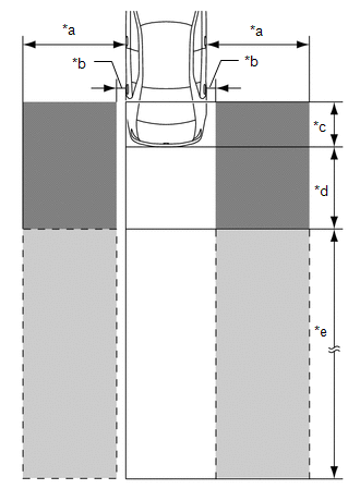
| *a | Within approximately 3.5 m (11.48 ft.) from Side of Vehicle |
| *b | Within approximately 0.5 m (1.64 ft.) from Side of Vehicle |
| *c | Within approximately 1 m (3.28 ft.) Forward of Rear Bumper |
| *d | Within approximately 3 m (9.84 ft.) Behind Rear Bumper |
| *e | Within approximately 3 m (9.84 ft.) to 60 m (196.86 ft.) from Rear Bumper |
.png) | Detection Area (for Vehicle in Blind Spot) |
 | Detection Area (for Rapidly Approaching Vehicle from Behind) |
(b) Operation description of the RCTA function
(1) Operation conditions:
- The blind spot monitor main switch (combination switch assembly) is on.
- The shift lever is in R.
- The vehicle speed is less than approximately 8 km/h (5 mph).
(2) Conditions in which a sensor can detect a vehicle
The RCTA function indicates detection of a vehicle in the detection area when both conditions are met:
- A vehicle is approaching this vehicle from diagonally behind.
- The vehicle speed is approximately 8 km/h (5 mph) to 28 km/h (18 mph).
(3) Detection area
Vehicles in the following areas can be detected:
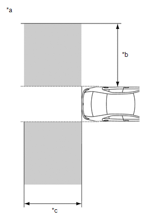
| *a | Vehicles in the following areas can be detected: |
| *b | Within approximately 5.5 to 20 m (18.04 to 65.62 ft.) from the side of the vehicle (detection area changes according to vehicle speed) |
| *c | Within approximately 6 m (19.69 ft.) behind the rear bumper |
OPERATION OF OUTER REAR VIEW MIRROR INDICATOR AND RCTA BUZZER (BLIND SPOT MONITOR BUZZER)
(a) Initial check
(1) When the blind spot monitor main switch (combination switch assembly) is turned on with the power switch on (IG), the outer rear view mirror indicator on each outer rear view mirror assembly illuminates for 3 seconds and the RCTA buzzer (blind spot monitor buzzer) sounds for 1 second.
(2) When the power switch is turned from off to on (IG) with the blind spot monitor main switch (combination switch assembly) on, the outer rear view mirror indicator on each outer rear view mirror assembly illuminates for 3 seconds.
(b) Operation for each function
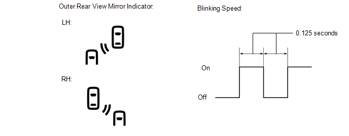
(1) Operation for blind spot monitor function
- When a sensor detects a vehicle in the blind spot area, the outer rear view mirror indicator on the outer rear view mirror assembly illuminates.
- While the sensor is detecting a vehicle in the detection area and the indicator is illuminated, if the turn signal switch is operated, the outer rear view mirror indicator on the outer rear view mirror assembly starts blinking as shown in the illustration.
(2) Operation for RCTA function
- When all of the operation conditions for the RCTA function are met, the outer rear view mirror indicators on the outer rear view mirror assembly blink for 2.5 seconds and the RCTA buzzer (blind spot monitor buzzer) sounds for 2.3 seconds as shown in the illustration.
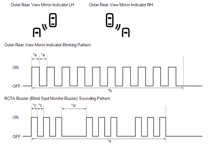
| *a | 0.125 seconds | *b | 2.5 seconds |
| *c | 0.1 seconds | *d | 0.4 seconds |
| *e | 2.3 seconds | - | - |
RCTA ICON OUTLINE
(a) If a vehicle approaching from the right or left at the rear of the vehicle is detected, the icon will illuminate on the multi-display.
w/ Parking Assist Monitor System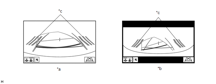
| *a | Narrow rear view screen | *b | Wide Rear View Screen |
| *c | RCTA Icon | - | - |
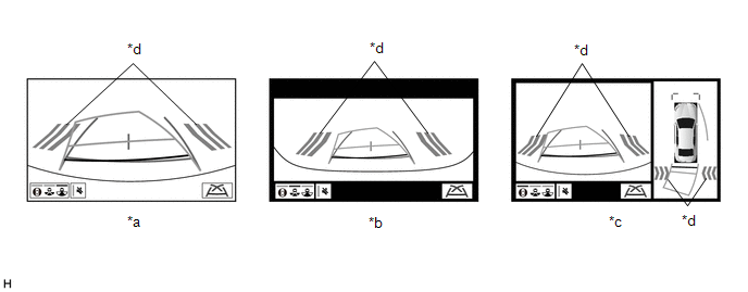
| *a | Narrow rear view screen | *b | Wide Rear View Screen |
| *c | Panoramic view and rear view screen | *d | RCTA Icon |
READ NEXT:
 How To Proceed With Troubleshooting
CAUTION / NOTICE / HINT HINT:
Use the following procedure to troubleshoot the blind spot monitor system.
*: Use the Techstream.
PROCEDURE 1. VEHICLE BROUGHT TO WORKSHOP
NEXT
Operation Check
OPERATION CHECK HINT: The blind spot monitor beam axis confirmation is performed to confirm whether the sensor's beam axis is correct, and perform adjustment of the beam axis by using reflector. BLIND
Problem Symptoms Table
PROBLEM SYMPTOMS TABLE NOTICE: When replacing the combination meter assembly, always replace it with a new one. If a combination meter assembly which was installed to another vehicle is used, the info
SEE MORE:
Dtc Check / Clear
DTC CHECK / CLEAR CHECK DTC (a) Connect the Techstream to the DLC3. (b) Turn the power switch on (IG). (c) Turn the Techstream on. (d) Enter the following menus: Chassis / Lane Control / Trouble Codes. (e) Check for details of the DTCs. Click here Chassis > Lane Control > Trouble Codes Te
Diagnostic Trouble Code Chart
DIAGNOSTIC TROUBLE CODE CHART Lane Tracing Assist System DTC No. Detection Item Link C1A7496 Steering Vibrator Component Internal Failure U012587 Lost Communication With Multi-axis Acceleration Sensor Module Missing Message U012687 Lost Communication with Steering
© 2016-2026 Copyright www.lexunx.com
