Lexus NX: Parts Location
PARTS LOCATION
ILLUSTRATION
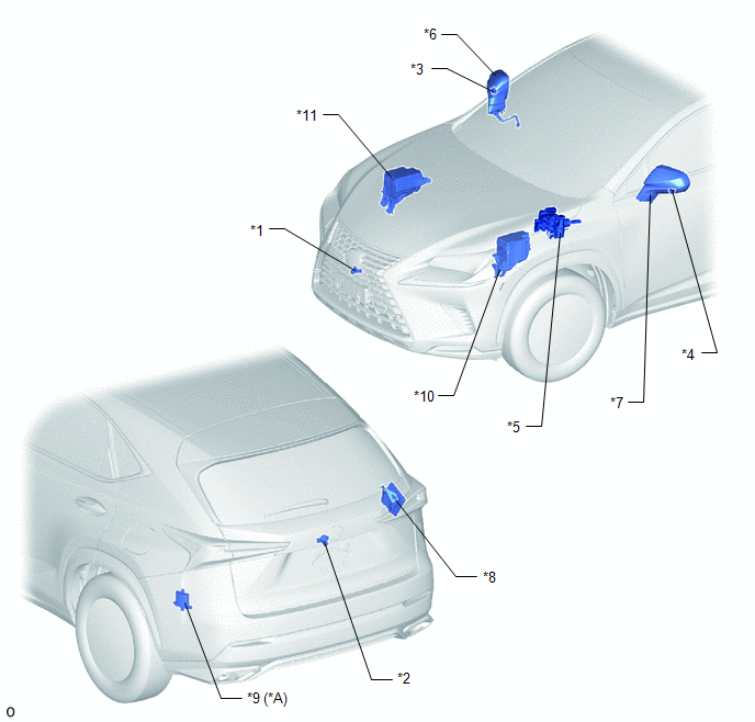
| *A | w/ Blind Spot Monitor System | - | - |
| *1 | FRONT TELEVISION CAMERA ASSEMBLY | *2 | REAR TELEVISION CAMERA ASSEMBLY |
| *3 | SIDE TELEVISION CAMERA ASSEMBLY RH | *4 | SIDE TELEVISION CAMERA ASSEMBLY LH |
| *5 | BRAKE BOOSTER WITH MASTER CYLINDER ASSEMBLY (SKID CONTROL ECU) | *6 | OUTER REAR VIEW MIRROR ASSEMBLY RH - OUTER MIRROR RETRACTOR RH |
| *7 | OUTER REAR VIEW MIRROR ASSEMBLY LH - OUTER MIRROR RETRACTOR LH | *8 | PARKING ASSIST ECU |
| *9 | BLIND SPOT MONITOR SENSOR LH | *10 | ENGINE ROOM RELAY BLOCK - ECU-B NO.4 FUSE |
| *11 | NO. 2 ENGINE ROOM RELAY BLOCK - ECU-IG NO.6 FUSE - ECU-B NO.2 FUSE | - | - |
ILLUSTRATION
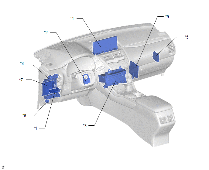
| *1 | NO. 2 COMBINATION SWITCH ASSEMBLY (PANORAMIC VIEW MONITOR MAIN SWITCH) | *2 | STEERING SENSOR |
| *3 | RADIO RECEIVER ASSEMBLY | *4 | MULTI-DISPLAY ASSEMBLY |
| *5 | CLEARANCE WARNING ECU ASSEMBLY | *6 | DLC3 |
| *7 | MAIN BODY ECU (MULTIPLEX NETWORK BODY ECU) | *8 | INSTRUMENT PANEL JUNCTION BLOCK ASSEMBLY - ECU-IG NO.1 FUSE - ACC FUSE |
| *9 | HYBRID VEHICLE CONTROL ECU | - | - |
READ NEXT:
 System Diagram
SYSTEM DIAGRAM Sender Receiver Signal Line
*: w/ Blind Spot Monitor System
Parking Assist ECU Multi-display Assembly Display GVIF cable Radio Receiver Assembly Multi-di
System Description
SYSTEM DESCRIPTION GENERAL (a) This system has front, passenger side, driver side and rear television camera assemblies mounted around the vehicle to display around the vehicle on the multi-display as
How To Proceed With Troubleshooting
CAUTION / NOTICE / HINT HINT:
Use the following procedure to troubleshoot the panoramic view monitor system.
*: Use the Techstream.
PROCEDURE 1. VEHICLE BROUGHT TO WORKSHOP
NEXT
SEE MORE:
Installation
INSTALLATION CAUTION / NOTICE / HINT CAUTION: Wear protective gloves. Sharp areas on the parts may injure your hands. HINT:
Use the same procedure for the RH and LH sides.
The procedure listed below is for the LH side.
PROCEDURE 1. INSTALL SEPARATE TYPE FRONT SEATBACK COVER LH HINT:
When
Noise Occurs or Sound Skips when Portable Player Plays
CAUTION / NOTICE / HINT HINT:
Perform this check with the portable player volume set at an appropriate level.
Make sure that there are no obstructions between the portable player and radio receiver assembly that may block signals, and that the portable player and radio receiver assembly are not
