- Mounted on the back door to transmit the rear view of the vehicle to the parking assist ECU.
- Has a color video camera that uses a Complementary Metal Oxide Semiconductor (CMOS) and a wide-angle lens
Lexus NX: System Description
Lexus NX Service Manual / Audio & Visual & Telematics / Park Assist / Monitoring / Panoramic View Monitor System / System Description
SYSTEM DESCRIPTION
GENERAL
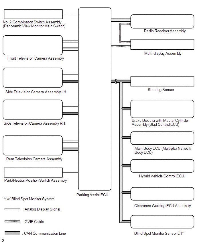
(a) This system has front, passenger side, driver side and rear television camera assemblies mounted around the vehicle to display around the vehicle on the multi-display assembly. The display panel also shows a composite view consisting of the area behind the vehicle and parking guidelines to assist the driver in parking the vehicle by monitoring the area around the vehicle.
(b) This system consists of the following components:
- *: w/ Blind Spot Monitor System
(1) Parking assist ECU
(2) No. 2 combination switch assembly (panoramic view monitor main switch)
(3) Rear television camera assembly
(4) Front television camera assembly
(5) Side television camera assembly LH
(6) Side television camera assembly RH
(7) Radio receiver assembly
(8) Multi-display assembly
(9) Steering sensor
(10) Brake booster with master cylinder assembly (skid control ECU)
(11) Main body ECU (multiplex network body ECU)
(12) Clearance warning ECU assembly
(13) Hybrid vehicle control ECU
(14) Blind spot monitor sensor LH*
(15) Park/neutral position switch assembly
(c) This system is equipped with a self-diagnosis system, which is operated from a designated window that appears on the display panel, just as in the audio and visual system*1 or navigation system*2.
- *1: w/ Audio and Visual System
- *2: w/ Navigation System
FUNCTION OF COMPONENTS
(a) The parking assist ECU controls the system by using information from the following components.
| Item | Function |
|---|---|
| Rear Television Camera Assembly | |
| Front Television Camera Assembly | Generates a video feed showing the front side of the vehicle and transmits the video to the parking assist ECU |
| Side Television Camera Assembly LH | Generates a video feed showing the left side of the vehicle and transmits the video to the parking assist ECU |
| Side Television Camera Assembly RH | Generates a video feed showing the right side of the vehicle and transmits the video to the parking assist ECU |
| Parking Assist ECU |
|
| No. 2 Combination Switch Assembly (panoramic view monitor main switch) | Sends switch operation signals to the parking assist ECU |
| Radio Receiver Assembly | Allows remote touch panel operations when the panoramic view monitor screen or diagnosis screen is displayed |
| Steering Sensor | Sends the steering angle signals and sensor status signals to the parking assist ECU via the CAN communication system |
| Brake Booster with Master Cylinder Assembly (Skid Control ECU) | Sends the vehicle speed signals, drive type signals, and system status signals to the parking assist ECU via the CAN communication system |
| Hybrid Vehicle Control ECU |
|
| Main Body ECU (Multiplex Network Body ECU) |
|
| Clearance Warning ECU Assembly | Sends information from each sonar via the CAN communication system |
Panoramic View Screen Display
(a) See-through view screen
(1) The entire area surrounding the vehicle is displayed.
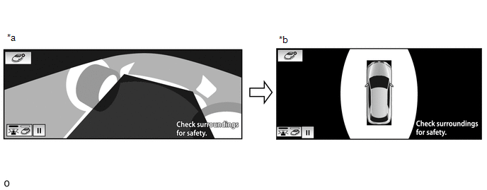
| *a | Vehicle interior view | *b | Upper view |
(b) Moving view screen
(1) The entire area surrounding the vehicle is displayed.
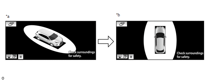
| *a | Slant upper view | *b | Upper view |
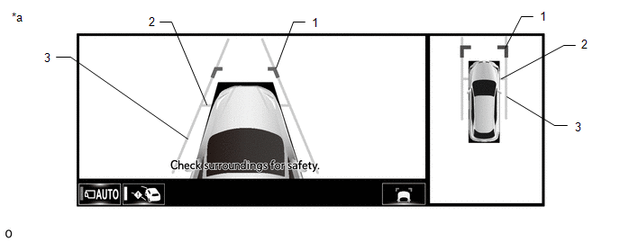
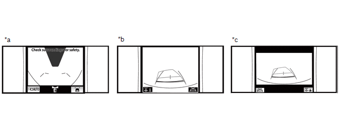
(c) Panoramic view and cornering view screen
(1) If the steering wheel is turned approximately 180° or more from the straight condition, the system automatically changes from the side clearance view to the cornering view.
The cornering view is displayed until the steering wheel is turned back within 90° of the straight condition.
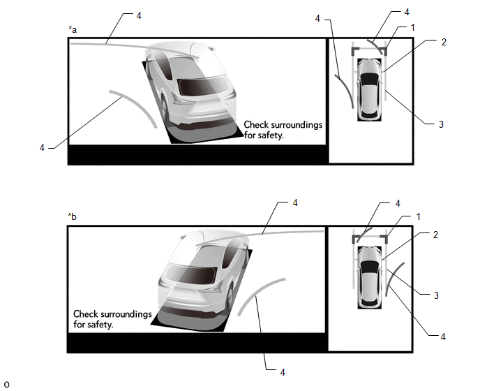
| *a | When turning left | *b | When turning right |
HINT:
Cornering view does not display when the vehicle speed is 12 km/h (7 mph) or more.
Panoramic View and Cornering View Screen Description| Signal | Name | Color |
|---|---|---|
| (1) | Front distance guide line | Blue |
| (2) | Front wheel ground contact line | Gray |
| (3) | Vehicle width parallel line | Gray |
| (4) | Forward estimated course line | Yellow |
(d) Panoramic view and wide front view screen
| *a | Estimated course line display mode | *b | Distance guide line display mode |
| Signal | Name | Color | Panoramic View and Wide Front View Screen | |
|---|---|---|---|---|
| Estimated course line display mode | Distance guide line display mode | |||
| (1) | Front distance guide line | Blue | Displayed | Displayed |
| (2) | Front wheel ground contact line | Yellow | Displayed | Not displayed |
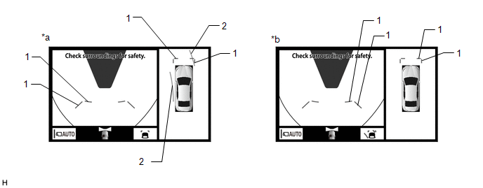
(e) Panoramic View and Side Clearance View Screen
| *a | When the outer rear view mirror assembly is deployed. | - | - |
| Signal | Name | Color |
|---|---|---|
| (1) | Front distance guide line | Blue |
| (2) | Front wheel ground contact line | Gray |
| (3) | Vehicle width parallel line | Gray |
(f) Panoramic view and wide rear view screen
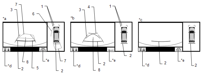
| *a | Estimated course line display mode | *b | Parking guide line display mode |
| *c | Distance guide line display mode | *d | Display mode switching button |
| *e | Guide line display mode switching button | - | - |
HINT:
The screen changes to the panoramic view and rear view screen when the display mode switch button or rear view screen is selected.
Panoramic View and Wide Rear View Screen Description| Signal | Name | Color | Panoramic View and Wide Rear View Screen | ||
|---|---|---|---|---|---|
| Estimated course line display mode | Parking guide line display mode | Distance guide line display mode | |||
| (1) | Front distance guide line | Blue | Displayed | Displayed | Displayed |
| (2) | Rear distance guide line | Red/Black | Displayed | Displayed | Displayed |
| (3) | Rear vehicle width extension line | Blue | Displayed | Displayed | Not displayed |
| (4) | Parking guide line | Blue | Not displayed | Displayed | Not displayed |
| (5) | Rear distance guide line | Blue | Displayed | Not displayed | Not displayed |
| (6) | Side estimated course line | Yellow | Displayed | Not displayed | Not displayed |
| (7) | Rear estimated course line | Yellow | Displayed | Not displayed | Not displayed |
| (8) | Vehicle center line | Blue | Displayed | Displayed | Not displayed |
(g) Panoramic view and rear view screen
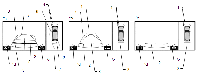
| *a | Estimated course line display mode | *b | Parking guide line display mode |
| *c | Distance guide line display mode | *d | Guide line display mode switching button |
| *e | Guide line display mode switching button | - | - |
HINT:
In the rear view screen, the screen display mode can be switched by pressing the guide line display mode switching button or rear view screen on the screen.
Panoramic View and Rear View Screen Description| Signal | Name | Color | Panoramic View and Rear View Screen | ||
|---|---|---|---|---|---|
| Estimated course line display mode | Parking guide line display mode | Distance guide line display mode | |||
| (1) | Front distance guide line | Blue | Displayed | Displayed | Displayed |
| (2) | Rear distance guide line | Red/Black | Displayed | Displayed | Displayed |
| (3) | Rear vehicle width extension line | Blue | Displayed | Displayed | Not displayed |
| (4) | Parking guide line | Blue | Not displayed | Displayed | Not displayed |
| (5) | Rear distance guide line | Blue | Displayed | Not displayed | Not displayed |
| (6) | Side estimated course line | Yellow | Displayed | Not displayed | Not displayed |
| (7) | Rear estimated course line | Yellow | Displayed | Not displayed | Not displayed |
| (8) | Vehicle center line | Blue | Displayed | Displayed | Not displayed |
(h) Side view screen
| *a | Side view and wide front view screen | *b | Side view and rear view screen |
| *c | Side view and wide rear view screen | - | - |
HINT:
Refer to the content of panoramic view and rear view screen and panoramic view and wide front view screen for information about the rear view and wide front view screens.
Panoramic View Screen Description
(a) Manual display mode
(1) When the No. 2 combination switch assembly (panoramic view monitor main switch) is pressed with the power switch on (IG) or (READY), the panoramic view monitor system switches to a screen shown below according to the shift lever position.
Screen Transition Chart (Manual Display Mode)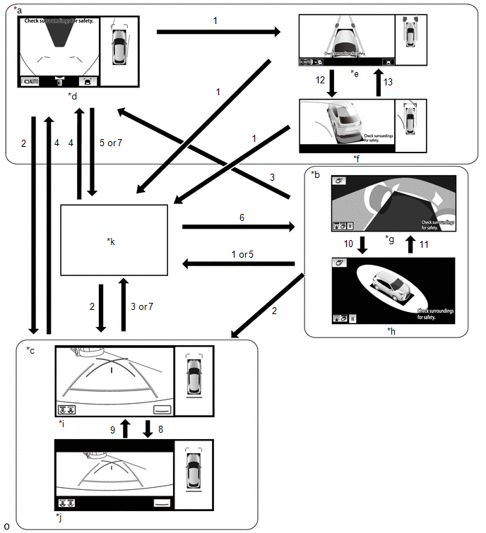
| *a | Shift lever not in P or R | *b | Shift lever in P and Intuitive parking assist system on |
| *c | Shift lever in R | *d | Panoramic view and wide front view screen |
| *e | Panoramic view and side clearance view screen | *f | Panoramic view and cornering view screen |
| *g | See-through view screen | *h | Moving view screen |
| *i | Panoramic view and rear view screen | *j | Panoramic view and wide rear view screen |
| *k | Navigation screen, etc. | - | - |
| No. | Screen Transition Conditions |
|---|---|
| (1) | Panoramic view monitor main switch is pressed |
| (2) | Shift lever is moved to R |
| (3) | Shift lever is moved to other than P or R |
| (4) | Shift lever is moved to other than P or R and operation (1) is performed |
| (5) | "MAP/VOICE" switches, etc. on the multi-display assembly are pressed |
| (6) | Operation (1) is performed with the shift lever in P |
| (7) | Shift lever is moved to P |
| (8) | Switch image mode button or rear view screen is selected |
| (9) | Switch image mode button or wide rear view screen is selected |
| (10) | Moving view switch button is selected |
| (11) | See through view switch button is selected |
| (12) | When the steering wheel is moved to the approximately 180° or more from the straight condition |
| (13) | The steering wheel is moved approximately 90° or less from the straight condition |
HINT:
If the panoramic view monitor main switch is pressed at a vehicle speed of approximately 12 km/h (7 mph) or lower, the panoramic view monitor system screen is displayed. If the vehicle speed exceeds approximately 12 km/h (7 mph), the display switches to the navigation screen or information settings screen.
(b) Screen transition chart (automatic display mode)
(1) When the shift lever is not in P or R, in addition to switching screens by pressing the No. 2 combination switch assembly (panoramic view monitor main switch), the automatic display mode can be selected by pressing the automatic display mode switching button.
| *a | Panoramic view and wide front view screen | *b | Panoramic view and side clearance view screen |
| *c | Automatic display mode | - | - |
| Automatic Display Mode Switching Button (Indicator in Button) | Screen Switching Mode |
|---|---|
| ON (Illuminated) | Automatic display mode |
| OFF (Not illuminated) | Manual display mode |
HINT:
- In the automatic display mode, press the No. 2 combination switch assembly (panoramic view monitor main switch) or panel switch to switch screens in the same way as the manual display mode.
- When switching to the navigation screen, etc. in the automatic display mode, the display switches to the screen that was displayed last. However, the display switches to the panoramic view and wide front view screen if the shift lever is not in P or R after the power switch is turned from off to on (IG).
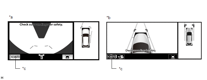
(2) The automatic display mode automatically switches the display according to the vehicle status.
Screen Transition Chart (Automatic Display Mode)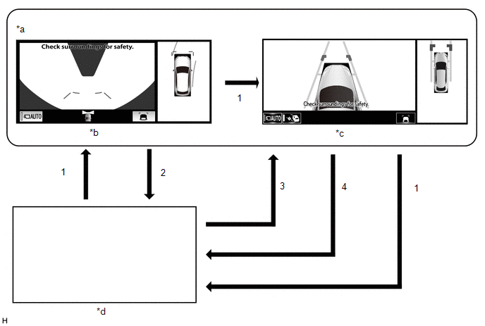
| *a | Shift lever not in P or R | *b | Panoramic view and wide front view screen |
| *c | Panoramic view and side clearance view screen | *d | Navigation screen, etc. |
| No. | Screen Transition Conditions |
|---|---|
| *: The panoramic view and wide front view screen is the first screen displayed after the power switch was turned off. | |
| (1) | No. 2 combination switch assembly (panoramic view monitor main switch) is pressed |
| (2) | Current location switches, etc. on the multi-display are pressed |
| (3) | Vehicle speed changes from above approximately 10 km/h (6 mph) to approximately 10 km/h (6 mph) or lower. The screen that was last displayed is displayed on the multi-display assembly.* |
| (4) | Vehicle speed changes from approximately 10 km/h (6 mph) or lower to above approximately 10 km/h (6 mph) |
(c) Panoramic View Zoom Function
(1) When detail within the image on the panoramic view screen is too small and difficult to see, the user can magnify the image by selecting one of the 4 areas on the panoramic view screen.
Screen Transition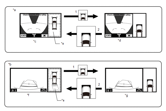
| *a | Panoramic view and wide front view screen displayed while shift lever is not in P or R | *b | Panoramic view and rear view screen displayed |
| *c | Panoramic view and wide front view screen | *d | Panoramic view and wide front view screen (Front left view magnified) |
| *e | Panoramic view screen | *f | Panoramic view and rear view screen |
| *g | Panoramic view and rear view screen (Front left view magnified) | - | - |
| No. | Screen Transition Conditions |
|---|---|
| (1) | Any of the 2 areas on the panoramic view screen is selected while the vehicle speed is approximately 12 km/h (7 mph) or less and the Intuitive parking assist system is turned on. |
| (2) | The remote touch switch is pressed on the panoramic view zoom screen, or either of the following conditions is met:
|
(d) When the outer rear view mirror assembly is retracted
(1) When the outer rear view mirrors are retracted, the screen changes according to the current screen display, as follows.
Screen Transition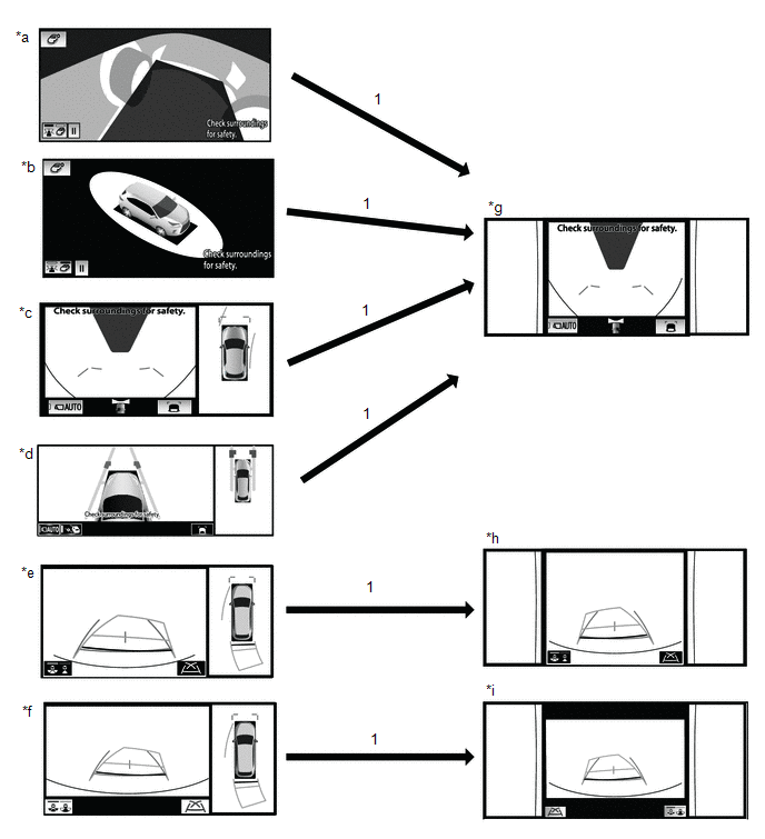
| *a | See through view screen | *b | Moving view screen |
| *c | Panoramic view and wide front view screen | *d | Panoramic view and side clearance view screen |
| *e | Panoramic view and rear view screen | *f | Panoramic view and wide rear view screen |
| *g | Side view and wide front view screen | *h | Side view and rear view screen |
| *i | Side view and wide rear view screen | - | - |
| No. | Screen Transition Conditions |
|---|---|
| (1) | When outer rear view mirror assembly is retracted |
OPERATION EXPLANATION
(a) The reverse position signal is sent from the shift lever position switch to the parking assist ECU when the shift lever is moved to R.
(b) An appropriate steering angle and timing information can be provided for the driver. This is based on the information from the steering angle sensor signal and the vehicle angle data signal that are sent to the parking assist ECU.
HINT:
The steering angle sensor signal is used to control parking assist only for estimated guide line mode.
COMMUNICATION SYSTEM OUTLINE
(a) CAN communication system
(1) The panoramic view monitor system uses CAN communication for data communications between the parking assist ECU and each ECU.
(2) If a problem occurs in the CAN communication line, the parking assist ECU outputs a CAN communication malfunction DTC. (To check, use the Techstream.)
Click here .gif)
(3) If a problem occurs in the CAN communication line, the parking assist ECU outputs a CAN communication malfunction DTC. (To check, use the multi-display assembly diagnosis screen.)
Click here
(4) If a CAN communication line malfunction DTC is output, repair the malfunction in the communication line and troubleshoot the panoramic view monitor system when data communication is normal.
(5) Since the CAN communication line has its own length and route, it cannot be repaired temporarily with a bypass wire, etc.
VIDEO SIGNALS
(a) Video signal circuit
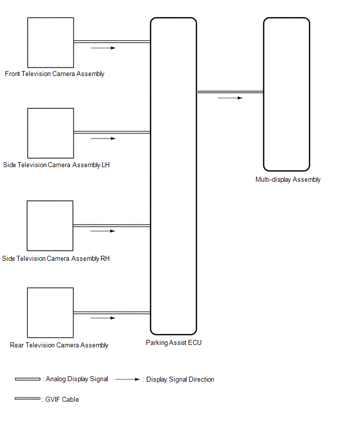
(1) Video signals from the front television camera assembly are input into the parking assist ECU via analog communication lines (vehicle wire harness).
(2) Video signals from the side television camera assembly LH are input into the parking assist ECU via analog communication lines (vehicle wire harness).
(3) Video signals from the side television camera assembly RH are input into the parking assist ECU via analog communication lines (vehicle wire harness).
(4) Video signals from the rear television camera assembly are input into the parking assist ECU via analog communication lines (vehicle wire harness).
(5) Video signals from the parking assist ECU are input into the multi-display assemly via GVIF cable.
(b) Screen display
(1) Video signals input from each camera are processed in the parking assist ECU and displayed on the multi-display assembly as the panoramic view monitor system screen.
DIAGNOSTIC FUNCTION OUTLINE
(a) This panoramic view monitor system has a diagnostic function displayed in the multi-display assembly. This function enables the calibration (adjustment and verification) of the panoramic view monitor system.
Click here
(b) The panoramic view monitor system can check the following items by using the Techstream.
| Item | Proceed to |
|---|---|
| DTC | |
| Data List / Active Test | |
CALIBRATION
(a) Use the panoramic view monitor system diagnosis screen for calibration and checking of the panoramic view monitor system.
Click here
NOTICE:
Part replacement and work performed during servicing may require calibration of the panoramic view monitor system and other systems.
Click here
READ NEXT:
 How To Proceed With Troubleshooting
CAUTION / NOTICE / HINT HINT:
Use the following procedure to troubleshoot the panoramic view monitor system.
*: Use the Techstream.
PROCEDURE 1. VEHICLE BROUGHT TO WORKSHOP
NEXT
Initialization
INITIALIZATION INITIALIZE PANORAMIC VIEW MONITOR SYSTEM (a) When "!" mark is displayed on the multi-display assembly, correct the steering angle neutral point using the following method. (1) Fully tur
Calibration
CALIBRATION ADJUST PANORAMIC VIEW MONITOR SYSTEM (a) This panoramic view monitor system can be set from the diagnostic screen of the multi-display assembly. (b) If the following operations are perform
SEE MORE:
Steering Pad Switch Circuit
DESCRIPTION This circuit sends an operation signal from the steering pad switch assembly to the radio receiver assembly. If there is an open in the circuit, the audio system cannot be operated using the steering pad switch assembly. If there is a short in the circuit, the same condition as when a sw
Dtc Check / Clear
DTC CHECK / CLEAR CHECK DTC (USING THE Techstream) (a) Turn the power switch off. (b) Connect the Techstream to the DLC3. (c) Turn the power switch on (IG). (d) Turn the Techstream on. (e) Enter the following menus: Chassis / EMPS / Trouble Codes. Chassis > EMPS > Trouble Codes (f) Read the DT
© 2016-2026 Copyright www.lexunx.com
