- Data continuity flag
- Steering angle signal
Lexus NX: System Diagram
Lexus NX Service Manual / Audio & Visual & Telematics / Park Assist / Monitoring / Panoramic View Monitor System / System Diagram
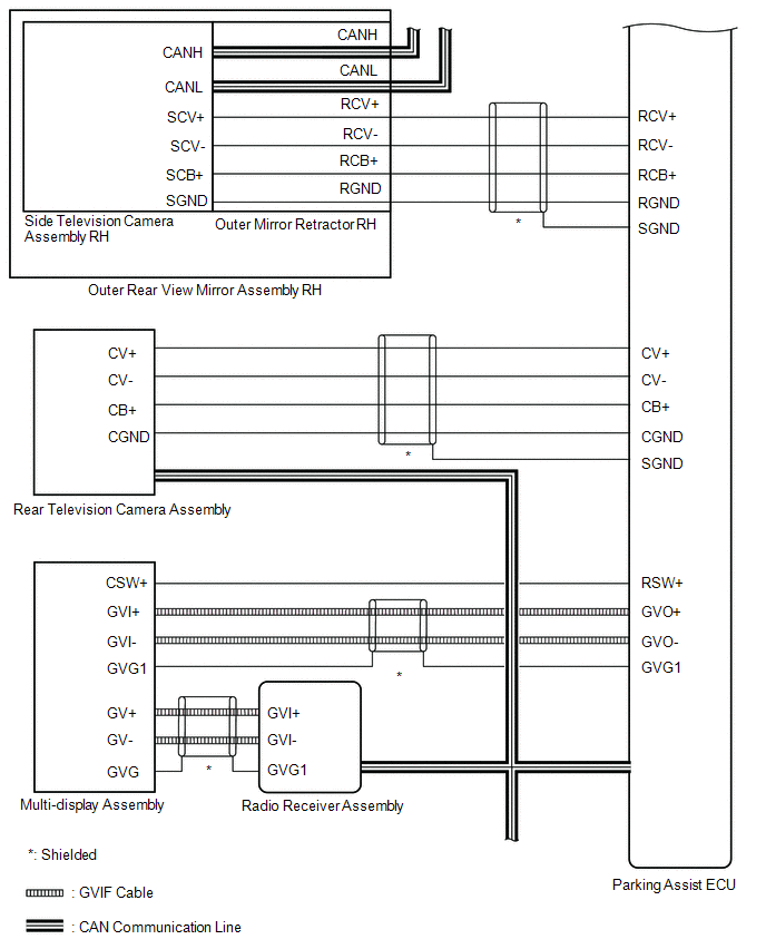
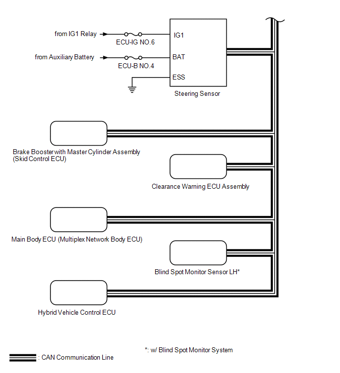
SYSTEM DIAGRAM
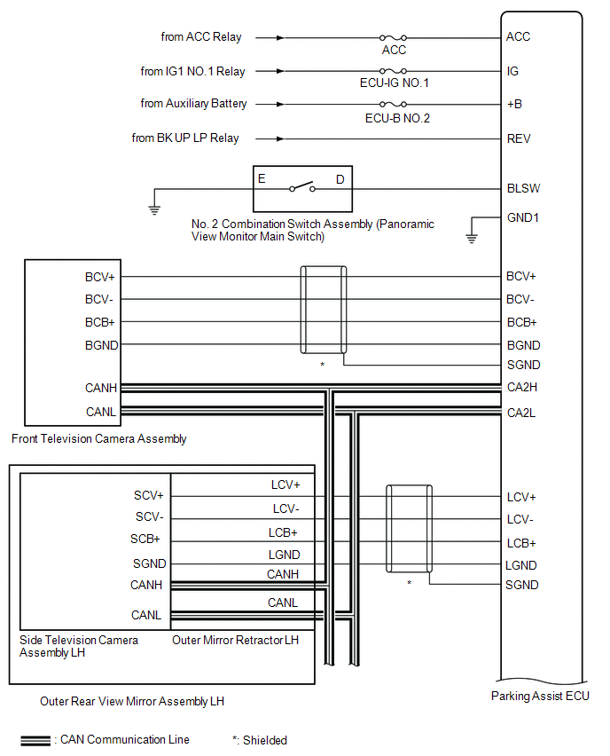
| Sender | Receiver | Signal | Line |
|---|---|---|---|
| *: w/ Blind Spot Monitor System | |||
| Parking Assist ECU | Multi-display Assembly | Display | GVIF cable |
| Radio Receiver Assembly | Multi-display Assembly | Display | GVIF cable |
| Steering Sensor | Parking Assist ECU | | CAN |
| Brake Booster with Master Cylinder Assembly (Skid Control ECU) | Parking Assist ECU |
| CAN |
| Clearance Warning ECU Assembly | Parking Assist ECU | Sensor information | CAN |
| Main Body ECU (Multiplex Network Body ECU) | Parking Assist ECU |
| CAN |
| Hybrid Vehicle Control ECU | Parking Assist ECU |
| CAN |
| Blind Spot Monitor Sensor LH* | Parking Assist ECU | RCTA information | CAN |
READ NEXT:
 System Description
SYSTEM DESCRIPTION GENERAL (a) This system has front, passenger side, driver side and rear television camera assemblies mounted around the vehicle to display around the vehicle on the multi-display as
How To Proceed With Troubleshooting
CAUTION / NOTICE / HINT HINT:
Use the following procedure to troubleshoot the panoramic view monitor system.
*: Use the Techstream.
PROCEDURE 1. VEHICLE BROUGHT TO WORKSHOP
NEXT
Initialization
INITIALIZATION INITIALIZE PANORAMIC VIEW MONITOR SYSTEM (a) When "!" mark is displayed on the multi-display assembly, correct the steering angle neutral point using the following method. (1) Fully tur
SEE MORE:
Diagnosis System
DIAGNOSIS SYSTEM DESCRIPTION (a) Smart access system with push-button start (for Entry Function) data and Diagnostic Trouble Codes (DTCs) can be read through the vehicle Data Link Connector 3 (DLC3). In some cases, a malfunction may be occurring in the smart access system with push-button start. Whe
Components
COMPONENTS ILLUSTRATION *1 DECK FLOOR BOX LH *2 NO. 3 DECK BOARD SUB-ASSEMBLY *3 REAR DECK FLOOR BOX *4 NEGATIVE AUXILIARY BATTERY TERMINAL N*m (kgf*cm, ft.*lbf): Specified torque - - ILLUSTRATION *1 DECK BOARD ASSEMBLY *2 DECK FLOOR BOX RH *3 NO. 1
© 2016-2026 Copyright www.lexunx.com
