Lexus NX: Clearance Warning Buzzer (for Front Side)
Lexus NX Service Manual / Audio & Visual & Telematics / Park Assist / Monitoring / Clearance Warning Buzzer (for Front Side)
Components
COMPONENTS
ILLUSTRATION
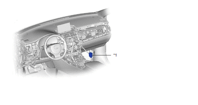
| *1 | NO. 1 CLEARANCE WARNING BUZZER | - | - |
READ NEXT:
 Clearance Warning Buzzer (for Rear Side)
ComponentsCOMPONENTS ILLUSTRATION *1 CLEARANCE WARNING BUZZER NO. 2 *2 TONNEAU COVER ASSEMBLY *3 UPPER DECK TRIM SIDE BOARD RH - - RemovalREMOVAL PROCEDURE 1. REMOVE TONNEAU C
Components
COMPONENTS ILLUSTRATION *1 DECK FLOOR BOX LH *2 NO. 3 DECK BOARD SUB-ASSEMBLY *3 REAR DECK FLOOR BOX *4 NEGATIVE AUXILIARY BATTERY TERMINAL N*m (kgf*cm, ft.*lbf): Specified
SEE MORE:
On-vehicle Inspection
ON-VEHICLE INSPECTION PROCEDURE 1. INSPECT RADIO SETTING CONDENSER (a) With the radio setting condenser installed, check that there is no looseness or other abnormalities. (b) Measure the resistance of the radio setting condenser according to the value(s) in the table below. Standard Resistance:
Open in Outer Mirror Indicator(Slave) (C1AB5)
DESCRIPTION This DTC is stored when the blind spot monitor sensor RH detects an open in the outer rear view mirror indicator RH. DTC No. Detection Item DTC Detection Condition Trouble Area Note C1AB5 Open in Outer Mirror Indicator(Slave) Both of the following conditions are met:
© 2016-2026 Copyright www.lexunx.com
