Lexus NX: Removal
REMOVAL
CAUTION / NOTICE / HINT
PROCEDURE
1. REMOVE ELECTRIC POWER STEERING COLUMN SUB-ASSEMBLY
Click here .gif)
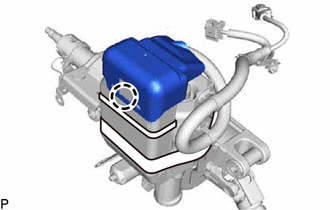
2. REMOVE POWER STEERING ECU ASSEMBLY
| (a) Detach the claw and remove the power steering ECU protector from the power steering ECU assembly. |
|
| (b) Remove the 2 cable ties and heat resistant tape. |
|
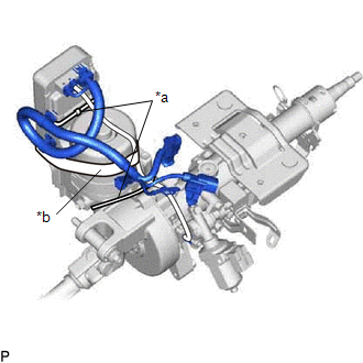
| (c) Disconnect the 3 connectors from the power steering ECU assembly. |
|
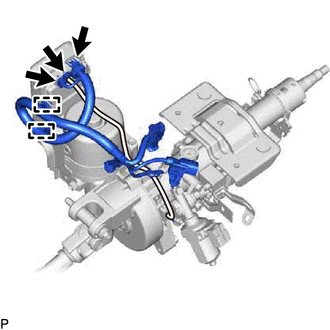
(d) Disconnect the 2 harness clamps from the harness bracket.
| (e) Remove the 3 bolts and power steering ECU assembly from the electric power steering column sub-assembly. |
|
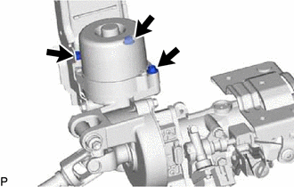
| (f) Remove the electric power steering motor shaft spacer from the electric power steering ECU assembly. |
|
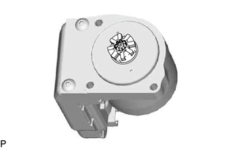
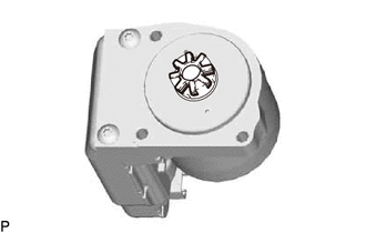
| (g) Remove the electric power steering motor shaft damper from the power steering ECU assembly. |
|
READ NEXT:
 Installation
INSTALLATION PROCEDURE 1. INSTALL POWER STEERING ECU ASSEMBLY (a) Install a new electric power steering motor shaft damper to the power steering ECU assembly. (b) Install a new electric power steering
Precaution
PRECAUTION HANDLING PRECAUTIONS FOR SRS AIRBAG SYSTEM (a) This vehicle is equipped with a Supplemental Restraint System (SRS). Failure to carry out service operations in the correct sequence could cau
SEE MORE:
Front Airbag Sensor Lost Communication (LH) (B1617,B1618)
DESCRIPTION The front airbag sensor LH circuit consists of the airbag ECU assembly and front airbag sensor LH. The front airbag sensor LH detects impacts to the vehicle and sends signals to the airbag ECU assembly to determine if the airbag should be deployed. DTC B1617 or B1618 is stored when a mal
Inspection
INSPECTION PROCEDURE 1. INSPECT CLEARANCE LIGHT ASSEMBLY LH (a) Apply battery voltage to the connector and check the light illumination condition. OK: Battery Connection Specified Condition Positive (+) → 3 (DRL) Negative (-) → 2 (E) Negative (-) → 4 (DRLC) White LED illuminates
