Lexus NX: Power Steering Warning Light Circuit
DESCRIPTION
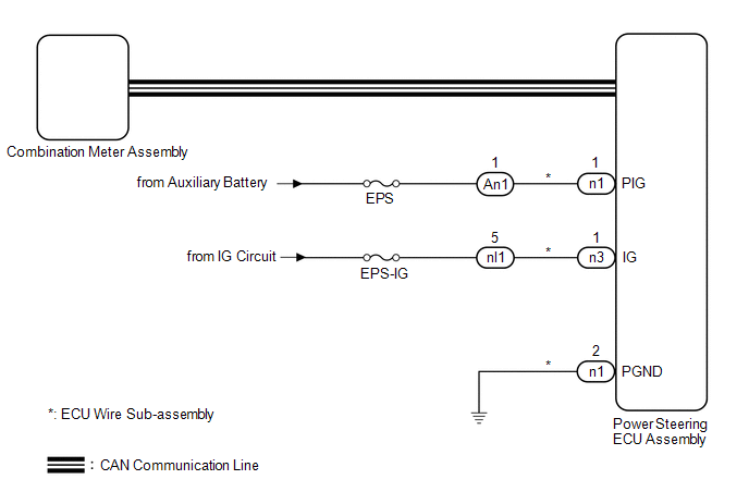
The power steering ECU is connected to the combination meter via CAN communication. If any of the following conditions are detected, the power steering warning light remains on.
- The circuit that supplies power source voltage to the power steering ECU assembly (terminal IG) is open.
- The power supply voltage to the power steering ECU assembly (terminals IG and PIG) drops.
WIRING DIAGRAM
CAUTION / NOTICE / HINT
NOTICE:
If the power steering ECU assembly has been replaced, perform assist map writing.
Click here .gif)
HINT:
Inspect the fuses for circuits related to this system before performing the following procedure.
PROCEDURE
| 1. | CHECK ASSIST LIMIT RECORD |
(a) Using the Techstream, read the Data List item "Assist Limit Record 1".
Chassis > EMPS > Data List| Tester Display | Measurement Item | Range | Normal Condition | Diagnostic Note |
|---|---|---|---|---|
| Assist Limit Record 1 | Information of assist limit that was used in the past or is currently in use (latest history) | Unrec, Mtr Overheat, Pow Vol Low, Pow Vol Low Prevent, Eng Stall, Ready OFF, Mtr Overload, Vhcl Spd Sig Malf, Batt Vol Keep | - | - |
| Tester Display |
|---|
| Assist Limit Record 1 |
HINT:
For the Data List item "Assist Limit Record 1", each item in the Range is described below.
| Range | Description |
|---|---|
| Mtr Overheat | When the vehicle is stopped or traveling at low speed, and steering operations are performed repeatedly or the steering wheel is turned all the way to the side and held there for a long time, assist may be limited in order to prevent overheating of the power steering motor assembly and power steering ECU assembly. After 10 minutes elapse with the engine stopped and no steering operations being performed, the system will return to normal. After recovering from the overheated condition, assist can be performed as usual. |
| Pow Vol Low | When insufficient battery charge, or battery degradation etc. causes the voltage to temporarily decrease, assist may be stopped. After the battery condition returns to normal, assist can be performed as usual. |
| Pow Vol Low Prevent | When insufficient battery charge, or battery degradation etc. causes the voltage to temporarily decrease, assist may be limited. After the battery condition returns to normal, assist can be performed as usual. |
| Eng Stall | When the engine stalls, battery charge becomes insufficient, so assist is stopped. After recovering from the engine stall, assist can be performed as usual. |
| Ready OFF | After Ready ON, if a malfunction in the HV system etc. causes a return to Ready OFF, the HV battery charge becomes insufficient, so assist is stopped. After returning to Ready ON state, assist can be performed as usual. |
| Mtr Overload | When the steering wheel cannot turn, such as when a road wheel is against a curb, if the driver continues to apply force to the steering wheel, current to the motor may be limited to prevent overheating. When the steering wheel is returned to a neutral position, assist can be performed as usual. |
| DC-DC Malf | If there is a malfunction in the DC-DC converter, etc., assist may be limited. After the DC-DC converter returns to normal, assist can be performed as usual. |
| Vhcl Spd Sig Malf | If the vehicle speed signal is abnormal due to a wheel speed sensor malfunction, etc., assist may be limited. |
| Batt Vol Keep | When insufficient battery charge, or battery degradation etc. causes the voltage to temporarily decrease, assist may be limited. After the battery condition returns to normal, assist can be performed as usual. |
(b) Based on the "Assist Limit Record 1" information, the following Data List items and the information from the customer interview, explain the situation to the customer.
Chassis > EMPS > Data List| Tester Display | Measurement Item | Range | Normal Condition | Diagnostic Note |
|---|---|---|---|---|
| Record 1 Key Cycle | Number of times that the power switch was turned on (IG) before Assist Limit Record 1 was stored | Min.: 0 times Max.: 65535 times | - | - |
| Record 1 Key Cycle Elapsed Time | Period of time that elapsed after the power switch was turned on (IG) before Assist Limit Record 1 was stored | Min.: 0.0 s Max.: 53687091.1 s | - | - |
| Tester Display |
|---|
| Record 1 Key Cycle |
| Record 1 Key Cycle Elapsed Time |
| Result | Proceed to |
|---|---|
| "Unrec" is displayed | A |
| Other than Unrec is displayed | B |
HINT:
If it is necessary to investigate further into the past, check the "Assist Limit Record 2" and "Assist Limit Record 3" information in the same way as "Assist Limit Record 1".
| B | .gif) | EXPLAIN THE CHECKED "ASSIST LIMIT RECORD 1" TO THE CUSTOMER, CROSS-CHECKING THE DATA LIST ITEMS WITH THE INFORMATION FROM THE CUSTOMER INTERVIEW. |
|
.gif)
| 2. | CHECK CONNECTOR CONNECTION CONDITION AND GROUND WIRE |
(a) Check the connection condition of the ECU wire sub-assembly and power steering ECU assembly connectors.
OK:
The ECU wire sub-assembly and power steering ECU assembly connectors are securely connected.
(b) Check that the ground wire is securely installed with the bolt.
Click here
OK:
The ground wire is securely installed with the bolt.
| NG | | CONNECT CONNECTOR OR INSTALL GROUND WIRE |
|
| 3. | CHECK FOR DTC (CAN COMMUNICATION SYSTEM) |
(a) Check for DTCs.
Click here
OK:
DTC is not output.
| NG | | GO TO CAN COMMUNICATION SYSTEM (HOW TO PROCEED WITH TROUBLESHOOTING) |
|
| 4. | READ VALUE USING TECHSTREAM (IG POWER SUPPLY) |
(a) Turn the power switch off.
(b) Connect the Techstream to the DLC3.
(c) Turn the power switch on (IG).
(d) Turn the Techstream on.
(e) Enter the following menus: Chassis / EMPS / Data List.
(f) Select the item "IG power supply" in the Data List and read the value displayed on the Techstream.
Chassis > EMPS > Data List| Tester Display | Measurement Item | Range | Normal Condition | Diagnostic Note |
|---|---|---|---|---|
| IG Power Supply | ECU power source voltage | Min.: 0.0000 V Max.: 20.1531 V | Power switch on (IG): 8 to 16 V | - |
| Tester Display |
|---|
| IG Power Supply |
OK:
The normal condition value is displayed on the Techstream.
| NG | | GO TO STEP 7 |
|
| 5. | READ VALUE USING TECHSTREAM (PIG POWER SUPPLY) |
(a) Turn the power switch off.
(b) Connect the Techstream to the DLC3.
(c) Turn the power switch on (IG).
(d) Turn the Techstream on.
(e) Enter the following menus: Chassis / EMPS / Data List.
(f) Select the item "PIG Power Supply" in the Data List and read the value displayed on the Techstream.
Chassis > EMPS > Data List| Tester Display | Measurement Item | Range | Normal Condition | Diagnostic Note |
|---|---|---|---|---|
| PIG Power Supply | Power source voltage to active motor | Min.: 0.0000 V Max.: 20.1531 V | Always: 9 to 16 V | - |
| Tester Display |
|---|
| PIG Power Supply |
OK:
The normal condition value is displayed on the Techstream.
| NG | | GO TO STEP 9 |
|
| 6. | CHECK COMBINATION METER ASSEMBLY |
(a) Reconnect the n1 and n3 power steering ECU assembly connectors.
(b) Perform the Active Test of the combination meter assembly using the Techstream.
Click here
| Tester Display |
|---|
| Indicat. EPS |
(c) Check the combination meter assembly.
OK:
The power steering warning light (red) turns on or off in accordance with the Techstream operation.
| OK | | REPLACE POWER STEERING ECU ASSEMBLY |
| NG | | GO TO METER / GAUGE SYSTEM |
| 7. | CHECK HARNESS AND CONNECTOR (IG POWER SUPPLY) |
| (a) Disconnect the nl1 ECU wire sub-assembly connector. |
|
.png)
(b) Turn the power switch on (IG).
(c) Measure the voltage according to the value(s) in the table below.
Standard Voltage:
| Tester Connection | Switch Condition | Specified Condition |
|---|---|---|
| nl1-5 (IG) - Body ground | Power switch on (IG) | 8 to 16 V |
| NG | | REPAIR OR REPLACE HARNESS OR CONNECTOR |
|
| 8. | CHECK ECU WIRE SUB-ASSEMBLY |
| (a) Connect the nl1 connector to the ECU wire sub-assembly. |
|
.png)
(b) Disconnect the n3 and n1 power steering ECU assembly connectors.
(c) Turn the power switch on (IG).
(d) Measure the voltage according to the value(s) in the table below.
Standard Voltage:
| Tester Connection | Switch Condition | Specified Condition |
|---|---|---|
| n3-1 (IG) - Body ground | Power switch on (IG) | 8 to 16 V |
(e) Turn the power switch off.
(f) Measure the resistance according to the value(s) in the table below.
Standard Resistance:
| Tester Connection | Condition | Specified Condition |
|---|---|---|
| n1-2 (PGND) - Body ground | Always | Below 1 Ω |
| OK | | REPLACE POWER STEERING ECU ASSEMBLY |
| NG | | REPAIR OR REPLACE ECU WIRE SUB-ASSEMBLY |
| 9. | CHECK HARNESS AND CONNECTOR (AUXILIARY BATTERY - ECU WIRE SUB-ASSEMBLY) |
| (a) Disconnect the An1 ECU wire sub-assembly connector. |
|
.png)
(b) Measure the voltage according to the value(s) in the table below.
Standard Voltage:
| Tester Connection | Condition | Specified Condition |
|---|---|---|
| An1-1 (PIG) - Body ground | Always | 9 to 16 V |
| NG | | REPAIR OR REPLACE HARNESS OR CONNECTOR |
|
| 10. | CHECK ECU WIRE SUB-ASSEMBLY |
| (a) Connect the An1 connector to the ECU wire sub-assembly. |
|
.png)
(b) Disconnect the n1 power steering ECU assembly connector.
(c) Measure the voltage according to the value(s) in the table below.
Standard Voltage:
| Tester Connection | Condition | Specified Condition |
|---|---|---|
| n1-1 (PIG) - Body ground | Always | 9 to 16 V |
(d) Measure the resistance according to the value(s) in the table below.
Standard Resistance:
| Tester Connection | Condition | Specified Condition |
|---|---|---|
| n1-2 (PGND) - Body ground | Always | Below 1 Ω |
| OK | | REPLACE POWER STEERING ECU ASSEMBLY |
| NG | | REPAIR OR REPLACE ECU WIRE SUB-ASSEMBLY |
READ NEXT:
 Precaution
PRECAUTION HANDLING PRECAUTIONS FOR SRS AIRBAG SYSTEM (a) This vehicle is equipped with a Supplemental Restraint System (SRS). Failure to carry out service operations in the correct sequence could cau
Parts Location
PARTS LOCATION ILLUSTRATION *1 POWER STEERING ECU ASSEMBLY - POWER STEERING MOTOR *2 ELECTRIC POWER STEERING COLUMN SUB-ASSEMBLY - TORQUE SENSOR *3 SKID CONTROL ECU (BRAKE BOOSTER WITH
SEE MORE:
Problem Symptoms Table
PROBLEM SYMPTOMS TABLE NOTICE: If the main body ECU (multiplex network body ECU) is replaced, refer to Registration. Click here HINT:
Use the table below to help determine the cause of problem symptoms. If multiple suspected areas are listed, the potential causes of the symptoms are listed in
Components
COMPONENTS ILLUSTRATION *1 DECK FLOOR BOX LH *2 NO. 3 DECK BOARD SUB-ASSEMBLY *3 REAR DECK FLOOR BOX *4 AUXILIARY BATTERY NEGATIVE TERMINAL N*m (kgf*cm, ft.*lbf): Specified torque - - ILLUSTRATION *1 HEADLIGHT DIMMER SWITCH ASSEMBLY *2 TILT AND TELESCOPIC
