Lexus NX: IG Power Source Circuit
DESCRIPTION
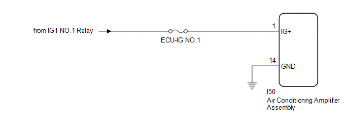
The main power source is supplied to the air conditioning amplifier assembly when the power switch is on (IG).
The power is used for operating the air conditioning amplifier assembly, servo motors, etc.
WIRING DIAGRAM
CAUTION / NOTICE / HINT
NOTICE:
Inspect the fuses for circuits related to this system before performing the following procedure.
PROCEDURE
| 1. | CHECK HARNESS AND CONNECTOR (AIR CONDITIONING AMPLIFIER ASSEMBLY - BATTERY AND BODY GROUND) |
| (a) Disconnect the air conditioning amplifier assembly connector. |
|
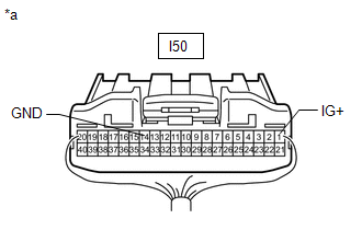
(b) Measure the voltage according to the value(s) in the table below.
Standard Voltage:
| Tester Connection | Switch Condition | Specified Condition |
|---|---|---|
| I50-1 (IG+) - Body ground | Power switch off | Below 1 V |
| I50-1 (IG+) - Body ground | Power switch on (IG) | 11 to 14 V |
(c) Measure the resistance according to the value(s) in the table below.
Standard Resistance:
| Tester Connection | Condition | Specified Condition |
|---|---|---|
| I50-14 (GND) - Body ground | Always | Below 1 Ω |
| OK | .gif) | PROCEED TO NEXT SUSPECTED AREA SHOWN IN PROBLEM SYMPTOMS TABLE |
.gif)
| NG | | REPAIR OR REPLACE HARNESS OR CONNECTOR |
READ NEXT:
 Back-up Power Source Circuit
DESCRIPTION The back-up power source circuit for the air conditioning amplifier assembly is shown below. Power is supplied even when the power switch is off. The power is used for diagnostic trouble c
Removal
REMOVAL PROCEDURE 1. RECOVER REFRIGERANT FROM REFRIGERATION SYSTEM Click here 2. DRAIN ENGINE COOLANT Click here 3. DISCONNECT AIR CONDITIONER TUBE AND ACCESSORY ASSEMBLY (a) Remove the bolt an
SEE MORE:
Speaker Circuit
DESCRIPTION If there is a short in a speaker circuit, the stereo component amplifier assembly detects it and stops output to the speakers. As a result, sound cannot be heard from the speakers even if there is no malfunction in the stereo component amplifier assembly, DCM (telematics transceiver)* or
Hybrid Powertrain Control Module (P0A1D-162,P0A1D-821,P0A1D-822,P0A1D-823)
DESCRIPTION The hybrid vehicle control ECU monitors its internal operation, it will store a DTC and perform fail-safe control if it detects the following malfunction. If the following DTC is output, replace the hybrid vehicle control ECU. DTC No. Detection Item DTC Detection Condition Troub
