Lexus NX: Radio Broadcast cannot be Received or Poor Reception
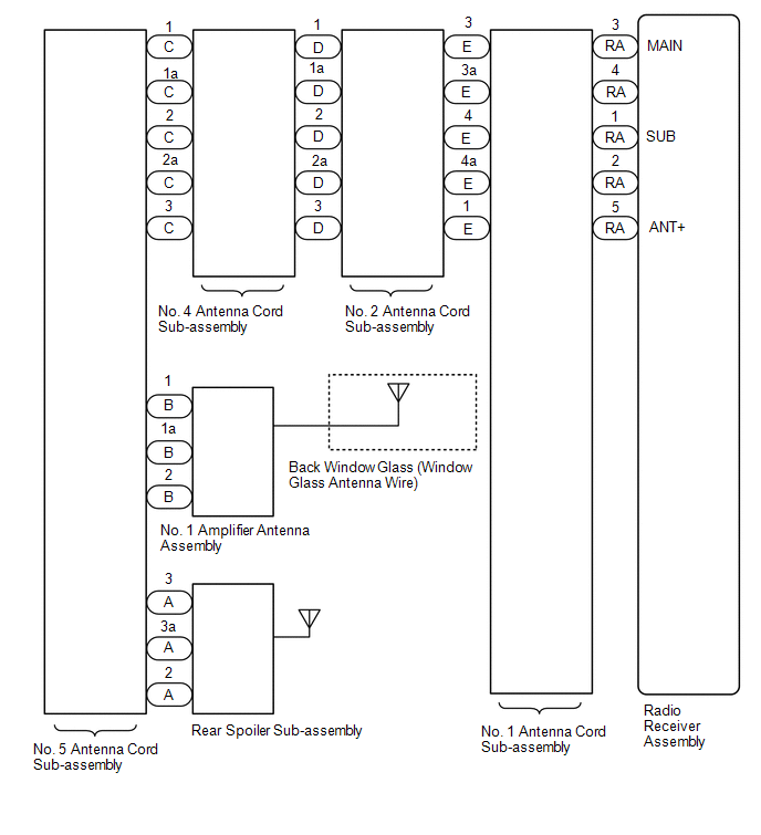
WIRING DIAGRAM
CAUTION / NOTICE / HINT
NOTICE:
When replacing the radio receiver assembly, always replace it with a new one.
If a radio receiver assembly which was installed to another vehicle is used, the following may occur:
- A communication malfunction DTC may be stored.
- The radio receiver assembly may not operate normally.
HINT:
Depending on the parts that are replaced during vehicle inspection or maintenance, performing initialization, registration or calibration may be needed. Refer to Precaution for Audio and Visual System.
Click here .gif)
PROCEDURE
| 1. | CHECK RADIO RECEIVER ASSEMBLY |
(a) Check the radio automatic station search function by activating it.
OK:
Automatic station search function stops on a station.
| OK | .gif) | USE SIMULATION METHOD TO CHECK |
|
.gif)
| 2. | CHECK OPTIONAL COMPONENTS |
(a) Check if any optional components that may decrease reception capacity, such as sunshade film or a telephone antenna, are installed.
OK:
Optional components are not installed.
NOTICE:
Do not remove optional components without the permission of the customer.
| NG | | REMOVE OPTIONAL COMPONENTS AND CHECK AGAIN (SEE NOTICE ABOVE) |
|
| 3. | CHECK RADIO RECEIVER ASSEMBLY |
| (a) Preparation for check (1) Disconnect the RA radio receiver assembly connector. |
|
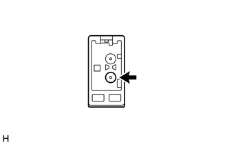
(b) Check for noise
(1) Turn the power switch on (ACC) with the radio receiver assembly connector connected.
(2) Turn the radio receiver assembly on and enter AM mode.
(3) Place a screwdriver, thin wire or other metal object on the radio receiver assembly antenna jack and check that noise can be heard from the speakers.
OK:
Noise can be heard from the speakers.
| NG | | REPLACE RADIO RECEIVER ASSEMBLY |
|
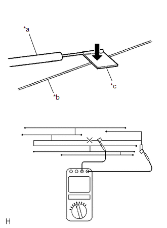
| 4. | CHECK BACK WINDOW GLASS (WINDOW GLASS ANTENNA WIRE) |
| (a) Check for continuity in the window glass antenna wire. HINT: Check for continuity at the center of each antenna wire as shown in the illustration. NOTICE: When cleaning the glass, wipe it in the direction of the wire with a soft dry cloth. Take care not to damage the wire. Do not use detergents or glass cleaners with abrasive ingredients. When measuring resistance, wrap a piece of tin foil around the tip of each probe and press the foil against the wire with your finger as shown in the illustration. OK: There is continuity in the window glass antenna wire. |
|
| NG | | REPAIR BACK WINDOW GLASS (WINDOW GLASS ANTENNA WIRE) |
|
| 5. | INSPECT RADIO RECEIVER ASSEMBLY |
| (a) Disconnect the RA radio receiver assembly connector. |
|
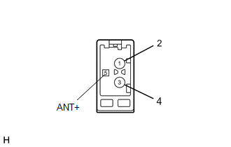
(b) Measure the voltage according to the value(s) in the table below.
Standard Voltage:
| Tester Connection | Switch Condition | Specified Condition |
|---|---|---|
| 5 (ANT+) - Body ground | Power switch on (ACC), radio switch on and FM or AM selected | 11 to 14 V |
| NG | | REPLACE RADIO RECEIVER ASSEMBLY |
|
| 6. | CHECK NO. 1 ANTENNA CORD SUB-ASSEMBLY |
| (a) Disconnect the antenna connector from the No. 2 antenna cord sub-assembly. |
|
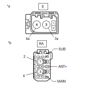
(b) Disconnect the antenna connector from the radio receiver assembly.
(c) Measure the resistance according to the value(s) in the table below.
Standard Resistance:
| Tester Connection | Condition | Specified Condition |
|---|---|---|
| E-3 - RA-3 (MAIN) | Always | Below 1 Ω |
| E-3a - RA-4 | Always | Below 1 Ω |
| E-4 - RA-1 (SUB) | Always | Below 1 Ω |
| E-4a - RA-2 | Always | Below 1 Ω |
| E-1 - RA-5 (ANT+) | Always | Below 1 Ω |
| E-3 - Body ground | Always | 10 kΩ or higher |
| E-3a - Body ground | Always | 10 kΩ or higher |
| E-4 - Body ground | Always | 10 kΩ or higher |
| E-4a - Body ground | Always | 10 kΩ or higher |
| E-1 - Body ground | Always | 10 kΩ or higher |
| NG | | REPLACE NO. 1 ANTENNA CORD SUB-ASSEMBLY |
|
| 7. | CHECK NO. 2 ANTENNA CORD SUB-ASSEMBLY |
| (a) Disconnect the antenna connector from the No. 4 antenna cord sub-assembly. |
|
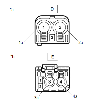
(b) Disconnect the antenna connector from the No. 1 antenna cord sub-assembly.
(c) Measure the resistance according to the value(s) in the table below.
Standard Resistance:
| Tester Connection | Condition | Specified Condition |
|---|---|---|
| D-1 - E-3 | Always | Below 1 Ω |
| D-1a - E-3a | Always | Below 1 Ω |
| D-2 - E-4 | Always | Below 1 Ω |
| D-2a - E-4a | Always | Below 1 Ω |
| D-3 - E-1 | Always | Below 1 Ω |
| D-1 - Body ground | Always | 10 kΩ or higher |
| D-1a - Body ground | Always | 10 kΩ or higher |
| D-2 - Body ground | Always | 10 kΩ or higher |
| D-2a - Body ground | Always | 10 kΩ or higher |
| D-3 - Body ground | Always | 10 kΩ or higher |
| NG | | REPLACE NO. 2 ANTENNA CORD SUB-ASSEMBLY |
|
| 8. | CHECK NO. 4 ANTENNA CORD SUB-ASSEMBLY |
| (a) Disconnect the antenna connector from the No. 5 antenna cord sub-assembly. |
|
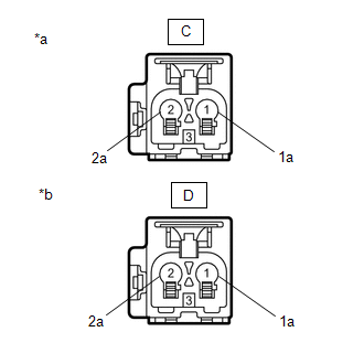
(b) Disconnect the antenna connector from the No. 2 antenna cord sub-assembly.
(c) Measure the resistance according to the value(s) in the table below.
Standard Resistance:
| Tester Connection | Condition | Specified Condition |
|---|---|---|
| C-1 - D-1 | Always | Below 1 Ω |
| C-1a - D-1a | Always | Below 1 Ω |
| C-2 - D-2 | Always | Below 1 Ω |
| C-2a - D-2a | Always | Below 1 Ω |
| C-3 - D-3 | Always | Below 1 Ω |
| C-1 - Body ground | Always | 10 kΩ or higher |
| C-1a - Body ground | Always | 10 kΩ or higher |
| C-2 - Body ground | Always | 10 kΩ or higher |
| C-2a - Body ground | Always | 10 kΩ or higher |
| C-3 - Body ground | Always | 10 kΩ or higher |
| NG | | REPLACE NO. 4 ANTENNA CORD SUB-ASSEMBLY |
|
| 9. | CHECK NO. 5 ANTENNA CORD SUB-ASSEMBLY |
| (a) Disconnect the antenna connector from the rear spoiler sub-assembly. |
|
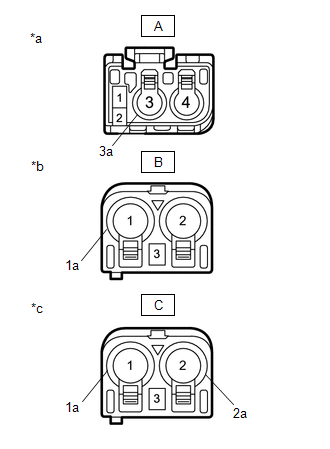
(b) Disconnect the antenna connector from the No. 1 amplifier antenna assembly.
(c) Disconnect the antenna connector from the No. 4 antenna cord sub-assembly.
(d) Measure the resistance according to the value(s) in the table below.
Standard Resistance:
| Tester Connection | Condition | Specified Condition |
|---|---|---|
| A-3 - C-1 | Always | Below 1 Ω |
| A-3a - C-1a | Always | Below 1 Ω |
| A-2 - C-3 | Always | Below 1 Ω |
| B-1 - C-2 | Always | Below 1 Ω |
| B-1a - C-2a | Always | Below 1 Ω |
| B-2 - C-3 | Always | Below 1 Ω |
| A-3 - Body ground | Always | 10 kΩ or higher |
| A-3a - Body ground | Always | 10 kΩ or higher |
| A-2 - Body ground | Always | 10 kΩ or higher |
| B-1 - Body ground | Always | 10 kΩ or higher |
| B-1a - Body ground | Always | 10 kΩ or higher |
| B-2 - Body ground | Always | 10 kΩ or higher |
| NG | | REPLACE NO. 5 ANTENNA CORD SUB-ASSEMBLY |
|
| 10. | CHECK NO. 1 AMPLIFIER ANTENNA ASSEMBLY |
(a) Replace the No. 1 amplifier antenna assembly with a new or known good one.
Click here
OK:
Radio broadcasts can be received normally.
| OK | | END (NO. 1 AMPLIFIER ANTENNA ASSEMBLY IS DEFECTIVE) |
|
| 11. | CHECK REAR SPOILER SUB-ASSEMBLY |
(a) Replace the rear spoiler sub-assembly with a new or known good one.
Click here
OK:
Radio broadcasts can be received normally.
| OK | | END (REAR SPOILER SUB-ASSEMBLY IS DEFECTIVE) |
| NG | | REPLACE RADIO RECEIVER ASSEMBLY |
READ NEXT:
 Illumination for Panel Switch does not Come on with Tail Switch ON
CAUTION / NOTICE / HINT NOTICE: When replacing the radio receiver assembly, always replace it with a new one. If a radio receiver assembly which was installed to another vehicle is used, the following
Display does not Dim when Light Control Switch is Turned ON
DESCRIPTION If the audio and visual system is turned on with the light control switch in the tail or head position, before AVC-LAN communication is established, the multi-display assembly dims accordi
Panel Switches do not Function
CAUTION / NOTICE / HINT NOTICE: When replacing the radio receiver assembly, always replace it with a new one. If a radio receiver assembly which was installed to another vehicle is used, the following
SEE MORE:
Clearance Warning Buzzer (for Rear Side)
ComponentsCOMPONENTS ILLUSTRATION *1 CLEARANCE WARNING BUZZER NO. 2 *2 TONNEAU COVER ASSEMBLY *3 UPPER DECK TRIM SIDE BOARD RH - - RemovalREMOVAL PROCEDURE 1. REMOVE TONNEAU COVER ASSEMBLY Click here 2. REMOVE UPPER DECK TRIM SIDE BOARD RH HINT: Use the same procedure des
Dtc Check / Clear
DTC CHECK / CLEAR CHECK FOR DTC (a) Turn the power switch off. (b) Connect the Techstream to the DLC3. (c) Turn the power switch on (IG). (d) Turn the Techstream on. (e) Enter the following menus: Chassis / Air suspension / Trouble Codes. Chassis > Air suspension > Trouble Codes HINT: When fre
