Lexus NX: Radio Receiver Power Source Circuit
DESCRIPTION
This is the power source circuit to operate the radio receiver assembly.
WIRING DIAGRAM

CAUTION / NOTICE / HINT
NOTICE:
- Inspect the fuses for circuits related to this system before performing the following procedure.
-
When replacing the radio receiver assembly, always replace it with a new one.
If a radio receiver assembly which was installed to another vehicle is used, the following may occur:
- A communication malfunction DTC may be stored.
- The radio receiver assembly may not operate normally.
HINT:
Depending on the parts that are replaced during vehicle inspection or maintenance, performing initialization, registration or calibration may be needed. Refer to Precaution for Audio and Visual System.
Click here .gif)
PROCEDURE
| 1. | CHECK HARNESS AND CONNECTOR (RADIO RECEIVER ASSEMBLY - BATTERY AND BODY GROUND) |
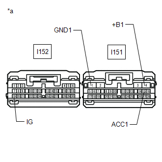
| (a) Disconnect the I151 and I152 radio receiver assembly connectors. |
|
(b) Measure the resistance according to the value(s) in the table below.
Standard Resistance:
| Tester Connection | Condition | Specified Condition |
|---|---|---|
| I151-1 (GND1) - Body ground | Always | Below 1 Ω |
(c) Measure the voltage according to the value(s) in the table below.
Standard Voltage:
| Tester Connection | Condition | Specified Condition |
|---|---|---|
| I151-4 (+B1) - I151-1 (GND1) | Power switch off | 11 to 14 V |
| I151-15 (ACC1) - I151-1 (GND1) | Power switch on (ACC) | 11 to 14 V |
| I152-19 (IG) - I151-1 (GND1) | Power switch on (IG) | 11 to 14 V |
| OK | .gif) | PROCEED TO NEXT SUSPECTED AREA SHOWN IN PROBLEM SYMPTOMS TABLE |
| NG | | REPAIR OR REPLACE HARNESS OR CONNECTOR |
READ NEXT:
 Components
COMPONENTS ILLUSTRATION *A w/o Power Back Door *B w/ Power Back Door *C for 10 Speakers *D for 14 Speakers *1 BACK DOOR CENTER GARNISH *2 BACK DOOR FINISH COVER LH *3
Removal
REMOVAL PROCEDURE 1. REMOVE BACK DOOR CENTER GARNISH Click here 2. REMOVE BACK DOOR SIDE GARNISH LH Click here 3. REMOVE BACK DOOR SIDE GARNISH RH Click here 4. REMOVE BACK DOOR TRIM BASE (w/
SEE MORE:
Wheel Speed Sensor Malfunction (C164D)
DESCRIPTION This DTC is stored when the clearance warning ECU assembly receives a wheel speed sensor (front speed sensor RH or front speed sensor LH, rear speed sensor RH or rear speed sensor LH) abnormality signal from the electronically controlled brake system via CAN communication. DTC No. D
Reassembly
REASSEMBLY PROCEDURE 1. INSTALL COOLER DRYER (a) Using pliers, install a new cooler dryer to the modulator. *1 Modulator (b) Apply sufficient compressor oil to the O-ring. Compressor Oil: ND-OIL 11 or equivalent (c) Using a 14 mm hexagon socket wrench, i
