Lexus NX: Seat Heater for Front Left Seat does not Operate
DESCRIPTION
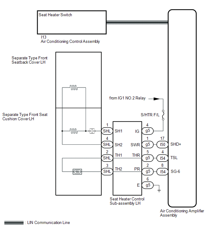
When the seat heater switch on air conditioning control assembly is operated, the air conditioning amplifier assembly receives the signal. The air conditioning amplifier assembly receives the signal and operates the front seat heater.
WIRING DIAGRAM
CAUTION / NOTICE / HINT
NOTICE:
-
If the auxiliary battery voltage is low, the seat heater system may not operate. When "High Power Consumption / Partial Limit On AC/Heater Operation" is displayed on the multi-information display in the combination meter assembly, inspect the auxiliary battery, referring to On-vehicle Inspection for the charging system.
Click here
.gif)
HINT:
If the auxiliary battery voltage is low, "Operation Limitation Control History Count (Level 1)" and "Operation Limitation Control History Count (Level 2) is counted.
Click here
-
If the auxiliary battery voltage is low, the seat heater system may not operate. Refer to Data List for the power steering system.
for Manual Tilt and Manual Telescopic Steering Column: Click here
for Power Tilt and Power Telescopic Steering Column: Click here
- Inspect the fuses for circuits related to this system before performing the following procedure.
PROCEDURE
| 1. | READ VALUE USING TECHSTREAM (FL Seat Heater Temperature) |
(a) Connect the Techstream to the DLC3.
(b) Turn the power switch on (IG).
(c) Turn the Techstream on.
(d) Enter the following menus: Body Electrical / Air Conditioner / Data List.
(e) Read the Data List according to the display on the Techstream.
Body Electrical > Air Conditioner > Data List| Tester Display | Measurement Item | Range | Normal Condition | Diagnostic Note |
|---|---|---|---|---|
| FL Seat Heater Temperature | Front seat LH heater temperature | -29.7°C to 59.55°C | Within range from 32 to 43°C (89 to 109°F) | Front seat heater is on |
| Tester Display |
|---|
| FL Seat Heater Temperature |
OK:
On the Techstream screen, the seat heater temperature is as specified in the normal condition column.
| OK | .gif) | REPLACE AIR CONDITIONING AMPLIFIER ASSEMBLY |
|
.gif)
| 2. | CHECK HARNESS AND CONNECTOR (SEAT HEATER CONTROL SUB-ASSEMBLY LH - BATTERY AND BODY GROUND) |
| (a) Disconnect the seat heater control sub-assembly LH connector. |
|
(b) Measure the resistance according to the value(s) in the table below.
Standard Resistance:
| Tester Connection | Condition | Specified Condition |
|---|---|---|
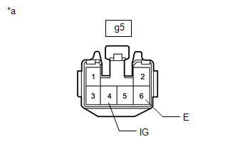
| g5-6 (E) - Body ground | Always | Below 1 Ω |
(c) Measure the voltage according to the value(s) in the table below.
Standard Voltage:
| Tester Connection | Switch Condition | Specified Condition |
|---|---|---|
| g5-4 (IG) - Body ground | Power switch on (IG) | 11 to 14 V |
| g5-4 (IG) - Body ground | Power switch off | Below 1 V |
| NG | | REPAIR OR REPLACE HARNESS OR CONNECTOR |
|
| 3. | INSPECT SEAT HEATER CONTROL SUB-ASSEMBLY LH |
| (a) Disconnect the g5 and SHL seat heater control sub-assembly LH connectors. |
|
(b) Measure the resistance according to the value(s) in the table below.
Standard Resistance:
| Tester Connection | Condition | Specified Condition |
|---|---|---|
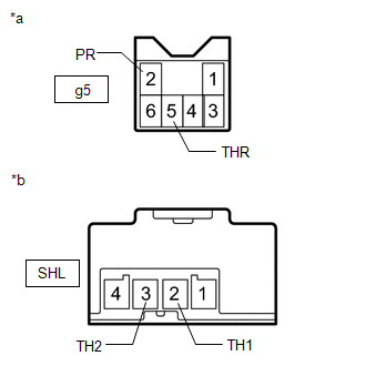
| g5-5 (THR) - SHL-2 (TH1) | Always | Below 1 Ω |
| g5-5 (THR) or SHL-2 (TH1) - Body ground | Always | 10 kΩ or higher |
| g5-2 (PR) - SHL-3 (TH2) | Always | Below 1 Ω |
| g5-2 (PR) or SHL-3 (TH2) - Body ground | Always | 10 kΩ or higher |
| NG | | REPLACE SEAT HEATER CONTROL SUB-ASSEMBLY LH |
|
| 4. | INSPECT SEPARATE TYPE FRONT SEAT CUSHION COVER LH |
(a) Remove the separate type front seat cushion cover LH.
Click here
(b) Inspect the separate type front seat cushion cover LH.
Click here
| NG | | REPLACE SEPARATE TYPE FRONT SEAT CUSHION COVER LH |
|
| 5. | INSPECT SEPARATE TYPE FRONT SEATBACK COVER LH |
(a) Remove the separate type front seatback cover LH.
Click here
(b) Inspect the separate type front seatback cover LH.
Click here
| NG | | REPLACE SEPARATE TYPE FRONT SEATBACK COVER LH |
|
| 6. | CHECK SEAT HEATER CONTROL SUB-ASSEMBLY LH |
(a) Temporarily replace the seat heater control sub-assembly LH with a new or known good one.
for Front Seat: Click here
for Rear Seat: Click here
(b) Check that the seat heater system is operated normally.
OK:
The seat heater system is operated normally.
| OK | | END (SEAT HEATER CONTROL SUB-ASSEMBLY LH WAS DEFECTIVE) |
|
| 7. | CHECK HARNESS AND CONNECTOR (AIR CONDITIONING AMPLIFIER ASSEMBLY - FRONT SEAT CONTROL SUB-ASSEMBLY LH) |
(a) Disconnect the I50 and I54 air conditioning amplifier assembly connectors.
(b) Disconnect the g5 seat heater control sub-assembly LH connector.
(c) Measure the resistance according to the value(s) in the table below.
Standard Resistance:
| Tester Connection | Condition | Specified Condition |
|---|---|---|
| I50-17 (SHD+) - g5-1 (SWR) | Always | Below 1 Ω |
| I50-17 (SHD+) or g5-1 (SWR) - Body ground | Always | 10 kΩ or higher |
| I54-4 (TSL) - g5-5 (THR) | Always | Below 1 Ω |
| I54-4 (TSL) or g5-5 (THR) - Body ground | Always | 10 kΩ or higher |
| I54-8 (SG-6) - g5-2 (PR) | Always | Below 1 Ω |
| I54-8 (SG-6) or g5-2 (PR) - Body ground | Always | 10 kΩ or higher |
| NG | | REPAIR OR REPLACE HARNESS OR CONNECTOR |
|
| 8. | CHECK AIR CONDITIONING AMPLIFIER ASSEMBLY |
(a) Temporarily replace the air conditioning amplifier assembly with a new or known good one.
Click here
(b) Check that the seat heater system is operated normally.
OK:
The seat heater system is operated normally.
| OK | | END (AIR CONDITIONING AMPLIFIER ASSEMBLY WAS DEFECTIVE) |
| NG | | REPLACE AIR CONDITIONING CONTROL ASSEMBLY |
READ NEXT:
 Seat Heater for Rear Right Seat does not Operate
DESCRIPTION When the refreshing seat switch is operated, the air conditioning amplifier assembly receives the signal via the LIN communication line, and operates the seat heater for the corresponding
Seat Heater for Rear Left Seat does not Operate
DESCRIPTION When the refreshing seat switch is operated, the air conditioning amplifier assembly receives the signal via the LIN communication line, and operates the seat heater for the corresponding
SEE MORE:
Diagnostic Trouble Code Chart
DIAGNOSTIC TROUBLE CODE CHART Panoramic View Monitor System DTC No. Detection Item Link C1614 ECU Malfunction C1621 Back Camera Power Supply Failure C1622 Open or Short Circuit in Back Camera Signal C1625 Open or Short in Steering Angle Sensor +B
Shut Down Signal Circuit
DESCRIPTION The cause of the malfunction may be a shutdown signal. Check whether there is a shutdown signal +B short circuit. Related Parts Check Area Inspection Step HSDN terminal voltage Check that the HSDN terminal voltage decreases while READY OFF (IG ON). If the voltage is low, the
