Lexus NX: Reassembly
REASSEMBLY
CAUTION / NOTICE / HINT
HINT:
- Use the same procedure for the RH and LH sides.
- The procedure listed below is for the LH side.
PROCEDURE
1. INSTALL NO. 2 MOULDING TAPE
(a) When using a new rear door rear upper outside moulding LH:
(1) Clean the surface of a new rear door rear upper outside moulding LH.
(b) When reusing the rear door rear upper outside moulding LH:
(1) Remove the double-sided tape from the rear door rear upper outside moulding LH.
(2) Wipe off any tape adhesive residue with cleaner.
(c) Install a new No. 2 moulding tape.
(1) Remove the peeling paper from the face of the No. 2 moulding tape.
HINT:
After removing the peeling paper, keep the exposed adhesive free from foreign matter.
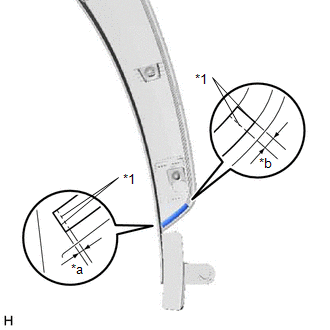
| (2) Install the No. 2 moulding tape as shown in the illustration. |
|
.png)
2. INSTALL REAR DOOR REAR OUTSIDE MOULDING PAD
(a) When using a new rear door rear upper outside moulding LH:
(1) Clean the surface of a new rear door rear upper outside moulding LH.
(b) When reusing the rear door rear upper outside moulding LH:
(1) Remove the double-sided tape from the rear door rear upper outside moulding LH.
(2) Wipe off any tape adhesive residue with cleaner.
(c) Install a new rear door rear outside moulding pad.
(1) Remove the peeling paper from the face of the rear door rear outside moulding pad.
HINT:
After removing the peeling paper, keep the exposed adhesive free from foreign matter.
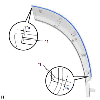
| (2) Install the rear door rear outside moulding pad as shown in the illustration. |
|
3. INSTALL REAR DOOR NO. 1 MOULDING PAD
(a) When using a new rear door rear upper outside moulding LH:
(1) Clean the surface of a new rear door rear upper outside moulding LH.
(b) When reusing the rear door rear upper outside moulding LH:
(1) Remove the double-sided tape from the rear door rear upper outside moulding LH.
(2) Wipe off any tape adhesive residue with cleaner.
(c) Install a new rear door No. 1 moulding pad.
(1) Remove the peeling paper from the face of the rear door No. 1 moulding pad.
HINT:
After removing the peeling paper, keep the exposed adhesive free from foreign matter.
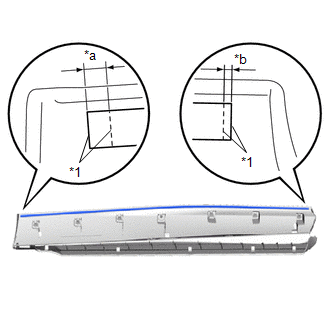
| (2) Install the rear door No. 1 moulding pad as shown in the illustration. |
|
4. INSTALL REAR DOOR UPPER OUTSIDE MOULDING PAD
(a) When using a new rear door lower outside moulding sub-assembly LH:
(1) Clean the surface of a new rear door lower outside moulding sub-assembly LH.
(b) When reusing the rear door lower outside moulding sub-assembly LH:
(1) Remove the double-sided tape from the front door outside moulding.
(2) Wipe off any tape adhesive residue with cleaner.
(c) Install a new rear door upper outside moulding pad.
(1) Remove the peeling paper from the face of the rear door upper outside moulding pad.
HINT:
After removing the peeling paper, keep the exposed adhesive free from foreign matter.
| (2) Install the rear door upper outside moulding pad as shown in the illustration. |
|
READ NEXT:
 Components
COMPONENTS ILLUSTRATION *1 DECK FLOOR BOX LH *2 NO. 3 DECK BOARD SUB-ASSEMBLY *3 REAR DECK FLOOR BOX *4 NEGATIVE AUXILIARY BATTERY TERMINAL N*m (kgf*cm, ft.*lbf): Specified
Removal
REMOVAL CAUTION / NOTICE / HINT HINT:
Use the same procedure for the RH and LH sides.
The procedure listed below is for the LH side.
PROCEDURE 1. PRECAUTION NOTICE: After the power switch off
SEE MORE:
Installation
INSTALLATION PROCEDURE 1. INSTALL BRAKE BOOSTER PUMP ASSEMBLY (a) Install the 2 brake actuator bracket cushions to the brake actuator bracket assembly. (b) Install the brake booster pump assembly, 2 brake booster pump bushings and 2 brake actuator case collars to the brake actuator bracket assemb
XM Tuner Antenna Disconnected (B15FE,B15FF)
DESCRIPTION These DTCs are stored when a malfunction occurs in the roof antenna assembly which is connected to the radio receiver assembly. DTC No. Detection Item DTC Detection Condition Trouble Area B15FE XM Tuner Antenna Disconnected The roof antenna assembly is not connected.
