
Lexus NX: Reclining Motor Circuit
DESCRIPTION
The fold seat control ECU receives switch operation signals from the No. 1 and No. 2 fold seat switches and rear power seat switch and activates the power seat motors. At this time, the Hall IC detects the actuation of the seatback and sends a seatback actuation signal to the fold seat control ECU. The fold seat control ECU uses signals from the Hall IC to detect if an object is caught or if any other abnormal condition has occurred.
WIRING DIAGRAM
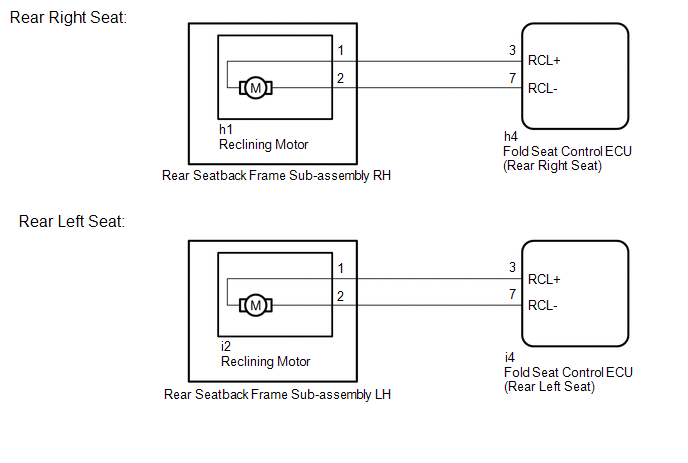
PROCEDURE
| 1. | INSPECT REAR SEATBACK FRAME SUB-ASSEMBLY (RECLINING MOTOR) |
(a) Remove the rear seatback frame sub-assembly.
Click here .gif)
(b) Inspect the rear seatback frame sub-assembly.
Click here
| NG | .gif) | REPLACE REAR SEATBACK FRAME SUB-ASSEMBLY |
|
.gif)
| 2. | CHECK HARNESS AND CONNECTOR (FOLD SEAT CONTROL ECU - REAR SEATBACK FRAME SUB-ASSEMBLY) |
(a) Rear Right Seat:
(1) Disconnect the h4 fold seat control ECU connector.
(2) Disconnect the h1 rear seatback frame sub-assembly connector.
(b) Rear Left Seat:
(1) Disconnect the i4 fold seat control ECU connector.
(2) Disconnect the i2 rear seatback frame sub-assembly connector.
(c) Measure the resistance according to the value(s) in the table below.
Standard Resistance:
Rear Right Seat
| Tester Connection | Condition | Specified Condition |
|---|---|---|
| h4-3 (RCL+) - h1-1 | Always | Below 1 Ω |
| h4-3 (RCL+) or h1-1 - Body ground | Always | 10 kΩ or higher |
| h4-7 (RCL-) - h1-2 | Always | Below 1 Ω |
| h4-7 (RCL-) or h1-2 - Body ground | Always | 10 kΩ or higher |
Rear Left Seat
| Tester Connection | Condition | Specified Condition |
|---|---|---|
| i4-3 (RCL+) - i2-1 | Always | Below 1 Ω |
| i4-3 (RCL+) or i2-1 - Body ground | Always | 10 kΩ or higher |
| i4-7 (RCL-) - i2-2 | Always | Below 1 Ω |
| i4-7 (RCL-) or i2-2 - Body ground | Always | 10 kΩ or higher |
| OK | | PROCEED TO NEXT SUSPECTED AREA SHOWN IN PROBLEM SYMPTOMS TABLE |
| NG | | REPAIR OR REPLACE HARNESS OR CONNECTOR |
READ NEXT:
 Rear Power Seat Switch Circuit
DESCRIPTION When the rear power seat switch is operated, a recline signal is sent to the fold seat control ECU. The ECU activates the power seat motor based on the signal from the rear power seat swit
Components
COMPONENTS ILLUSTRATION *1 BENCH TYPE REAR SEAT CUSHION ASSEMBLY *2 DECK BOARD ASSEMBLY *3 NO. 2 BATTERY SERVICE COVER BOARD *4 NO. 3 BATTERY SERVICE COVER BOARD *5 TONNEAU C
SEE MORE:
PBD Unit Pulse Sensor LH Circuit (B2226)
DESCRIPTION This DTC is output when the multiplex network door ECU detects a power back door unit assembly set LH pulse malfunction. DTC No. Detection Item DTC Detection Condition Trouble Area B2226 PBD Unit Pulse Sensor LH Circuit Multiplex network door ECU detects power back door
Footwell Light Circuit
DESCRIPTION The main body ECU (multiplex network body ECU) controls the operation of the following lights:
No. 1 interior illumination light assembly LH
No. 1 interior illumination light assembly RH
WIRING DIAGRAM CAUTION / NOTICE / HINT NOTICE:
Inspect the fuses for circuits related to
