Lexus NX: Removal
REMOVAL
CAUTION / NOTICE / HINT
CAUTION:
As the engine assembly with transaxle is extremely heavy, the engine lifter may suddenly drop if the instructions listed in the repair manual are not followed. Therefore, always follow the instructions listed in the repair manual when performing this procedure.
PROCEDURE
1. RECOVER REFRIGERANT FROM REFRIGERATION SYSTEM
Click here .gif)
2. DISCHARGE FUEL SYSTEM PRESSURE
Click here
3. PRECAUTION
NOTICE:
After turning the power switch is turned off, there may be a waiting time before disconnecting the auxiliary negative (-) battery terminal.
Click here
4. REMOVE NO. 3 DECK BOARD SUB-ASSEMBLY
Click here
5. REMOVE REAR DECK FLOOR BOX
Click here
6. REMOVE DECK FLOOR BOX LH
Click here
7. DISCONNECT CABLE FROM NEGATIVE AUXILIARY BATTERY TERMINAL
Click here
8. REMOVE BATTERY SERVICE HOLE COVER
Click here
9. REMOVE HYBRID BATTERY SERVICE PLUG COVER
Click here
10. REMOVE SERVICE PLUG GRIP
Click here
11. ALIGN FRONT WHEELS FACING STRAIGHT AHEAD
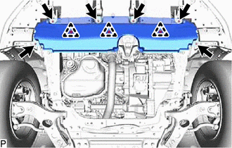
12. REMOVE NO. 1 ENGINE UNDER COVER ASSEMBLY
| (a) Remove the 2 screws, 4 bolts, 3 clips and No. 1 engine under cover assembly. |
|
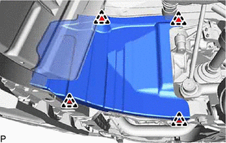
13. REMOVE REAR ENGINE UNDER COVER RH
| (a) Remove the 4 clips and rear engine under cover RH. |
|
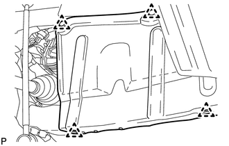
14. REMOVE REAR ENGINE UNDER COVER LH
| (a) Remove the 4 clips and rear engine under cover LH. |
|
15. REMOVE FRONT FLOOR COVER CENTER LH
Click here
16. DRAIN ENGINE COOLANT
Click here
17. DRAIN ENGINE OIL
Click here
18. DRAIN COOLANT (for Inverter Coolant)
Click here
19. DRAIN HYBRID TRANSAXLE FLUID
Click here
20. REMOVE RADIATOR SUPPORT OPENING COVER
Click here
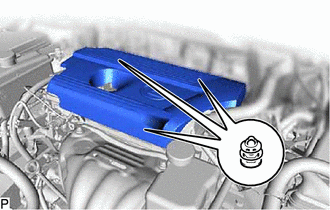
21. REMOVE NO. 1 ENGINE COVER SUB-ASSEMBLY
| (a) Remove the 3 pins and the No. 1 engine cover sub-assembly. NOTICE: Be sure to lift the No. 1 engine cover sub-assembly upwards when removing. Pulling the No. 1 engine cover sub-assembly towards you may damage the No. 1 engine cover sub-assembly. |
|
22. REMOVE AIR CLEANER CAP SUB-ASSEMBLY
Click here
23. REMOVE AIR CLEANER FILTER ELEMENT SUB-ASSEMBLY
(a) Remove the air cleaner filter element sub-assembly.
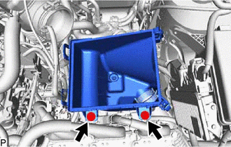
24. REMOVE AIR CLEANER CASE SUB-ASSEMBLY
| (a) Remove the 2 bolts and the air cleaner case sub-assembly. |
|
25. REMOVE INVERTER WITH CONVERTER ASSEMBLY
Click here
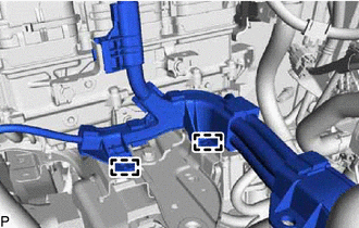
26. DISCONNECT NO. 2 FLOOR WIRE
CAUTION:
Be sure to wear insulated gloves.
NOTICE:
Wrap insulation tape round the removed terminals to insulate them.
| (a) Disconnect the 2 clamps and No. 2 floor wire from the inverter bracket. |
|
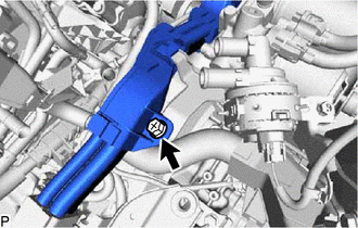
| (b) Remove the bolt. |
|
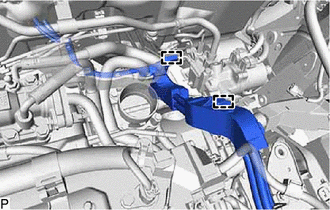
| (c) Disconnect the 2 clamps and No. 2 floor wire from the hybrid vehicle transaxle assembly. |
|
27. REMOVE INVERTER WATER PUMP WITH MOTOR ASSEMBLY
| (a) Remove the 2 bolts and the inverter water pump with motor assembly from the inverter bracket. |
|
28. REMOVE INVERTER BRACKET ASSEMBLY
| (a) Remove the 5 bolts and inverter bracket assembly. |
|
29. REMOVE ECM
Click here
30. DISCONNECT RADIATOR RESERVE TANK ASSEMBLY
(a) Remove the 2 bolts and disconnect the radiator reserve tank assembly.
31. REMOVE FAN AND GENERATOR V BELT
Click here
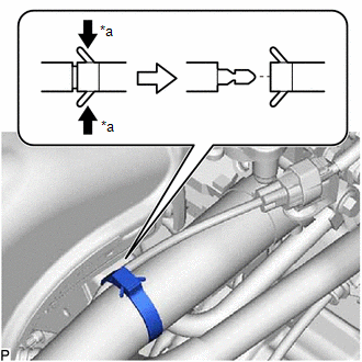
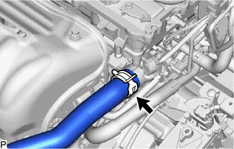
32. DISCONNECT NO. 2 RADIATOR HOSE
| (a) Slide the hose clip and disconnect the No. 2 radiator hose from the water inlet. |
|
33. REMOVE RADIATOR HOSE HOSE CLAMP
| (a) Remove the radiator hose hose clamp. |
|
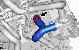
34. DISCONNECT NO. 1 RADIATOR HOSE
| (a) Slide the hose clip and disconnect the No. 1 radiator hose from the cylinder head sub-assembly. |
|
35. DISCONNECT DISCHARGE HOSE SUB-ASSEMBLY
Click here
36. DISCONNECT SUCTION HOSE SUB-ASSEMBLY
Click here
37. REMOVE NO. 3 INVERTER COOLING HOSE
| (a) Slide the hose clip and remove the No. 3 inverter cooling hose from the hybrid vehicle transaxle assembly. |
|
38. REMOVE NO. 5 INVERTER COOLING HOSE
| (a) Slide the hose clip and remove the No. 5 inverter cooling hose from the transmission oil cooler assembly. |
|
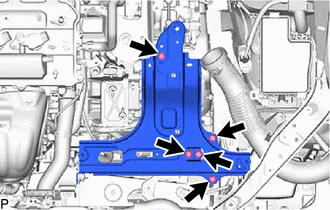
39. DISCONNECT GROUND WIRE
| (a) Remove the bolt, detach the 2 wire harness clamps and disconnect the ground wire. |
|
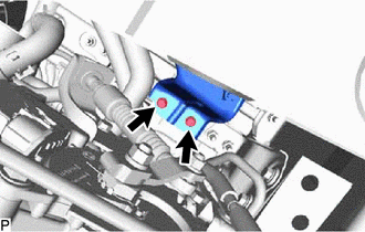
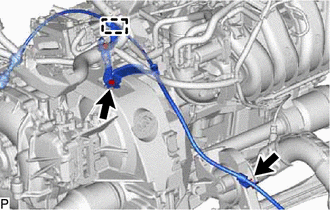
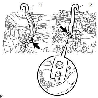
40. DISCONNECT WIRE HARNESS
| (a) Remove the bolt, detach the 3 wire harness clamps and disconnect the wire harness. |
|
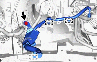
| (b) Remove the nut. |
|
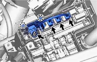
(c) Disconnect the 3 connectors and detach the 2 claws to disconnect the wire harness from the No. 1 engine room relay block.
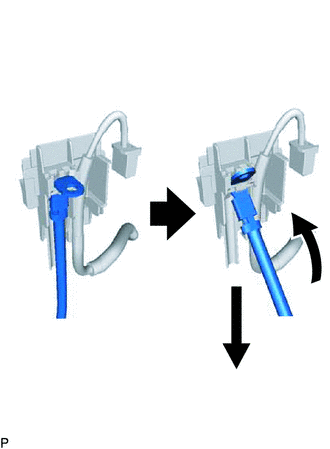
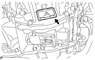
| (d) Disconnect the terminal from the No. 1 engine room relay block side cover as shown in the illustration. |
|
41. DISCONNECT FUEL TUBE SUB-ASSEMBLY
Click here
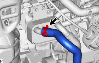
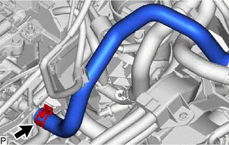
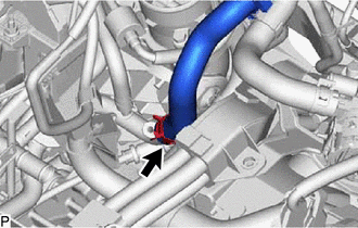
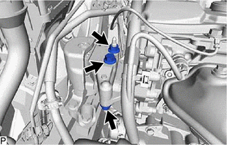
42. DISCONNECT HEATER WATER INLET HOSE
| (a) Slide the hose clamp and disconnect the heater water inlet hose from the cylinder head sub-assembly. |
|
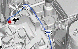
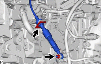
43. DISCONNECT HEATER WATER OUTLET HOSE
| (a) Slide the hose clamp and disconnect the heater water outlet hose from the No. 1 EGR pipe. |
|
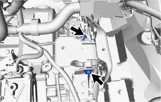
44. DISCONNECT TRANSMISSION CONTROL CABLE ASSEMBLY
| (a) Detach the clamp and disconnect the transmission control cable assembly from the bracket. |
|
(b) Remove the 2 bolts and disconnect the transmission control cable assembly from the hybrid vehicle transaxle assembly and rear engine mounting insulator.
| (c) Remove the nut and disconnect the transmission control cable assembly from the control shaft lever. |
|
(d) Remove the clip and disconnect the transmission control cable assembly from the control cable bracket.
45. REMOVE COLUMN HOLE COVER SILENCER SHEET
Click here
46. DISCONNECT NO. 2 STEERING INTERMEDIATE SHAFT ASSEMBLY
Click here
47. DISCONNECT NO. 1 STEERING COLUMN HOLE COVER SUB-ASSEMBLY
Click here
48. REMOVE FRONT AXLE SHAFT NUT LH
Click here
49. REMOVE FRONT AXLE SHAFT NUT RH
HINT:
Use the same procedure described for the LH side.
50. DISCONNECT FRONT SPEED SENSOR LH
Click here
51. DISCONNECT FRONT SPEED SENSOR RH
HINT:
Use the same procedure described for the LH side.
52. DISCONNECT FRONT STABILIZER LINK ASSEMBLY LH
Click here
53. DISCONNECT FRONT STABILIZER LINK ASSEMBLY RH
HINT:
Use the same procedure described for the LH side.
54. DISCONNECT TIE ROD END SUB-ASSEMBLY LH
Click here
55. DISCONNECT TIE ROD END SUB-ASSEMBLY RH
HINT:
Use the same procedure described for the LH side.
56. DISCONNECT FRONT LOWER NO. 1 SUSPENSION ARM SUB-ASSEMBLY LH
Click here
57. DISCONNECT FRONT LOWER NO. 1 SUSPENSION ARM SUB-ASSEMBLY RH
HINT:
Use the same procedure described for the LH side.
58. REMOVE FRONT DRIVE SHAFT ASSEMBLY LH
Click here
59. REMOVE FRONT DRIVE SHAFT HOLE SNAP RING LH
Click here
60. REMOVE FRONT DRIVE SHAFT ASSEMBLY RH
Click here
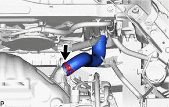
61. REMOVE FLYWHEEL HOUSING UNDER COVER
| (a) Remove the flywheel housing under cover. |
|
62. REMOVE FRONT EXHAUST PIPE SUB-ASSEMBLY
Click here
63. REMOVE FRONT SUSPENSION MEMBER REINFORCEMENT LH
Click here
64. REMOVE FRONT SUSPENSION MEMBER REINFORCEMENT RH
Click here
65. INSTALL ENGINE HANGER
| (a) Install the 2 engine hangers with the 2 bolts as shown in the illustration. Torque: 43 N·m {438 kgf·cm, 32 ft·lbf}
|
|
66. REMOVE ENGINE ASSEMBLY WITH TRANSAXLE
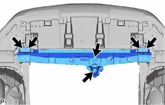
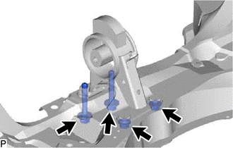
| (a) Remove the 6 bolts and front crossmember sub-assembly. |
|
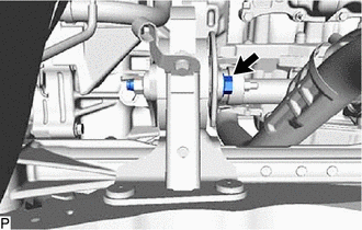
| (b) Remove the through bolt, nut and front engine mounting insulator. NOTICE: While holding the nut in place, loosen the through bolt. |
|
(c) Set an engine lifter underneath the engine.
NOTICE:
- Place the engine on wooden blocks or equivalent so that the engine is level.
-
To prevent coolant leaks, do not position the height adjustment attachments or plate lift attachments under the No. 2 motor water jacket cover assembly.
*1
No. 2 Motor Water Jacket Cover Assembly
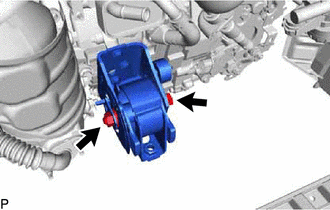
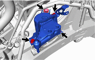
| (d) Remove the bolt and 2 nuts and disconnect the engine mounting insulator sub-assembly RH. |
|
| (e) Remove the through bolt and nut and disconnect the engine mounting insulator LH. |
|
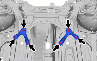
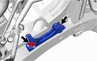
| (f) Remove the 6 bolts, front suspension member rear brace RH and front suspension member rear brace LH. |
|
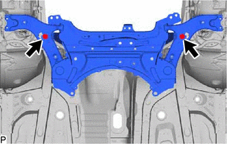
| (g) Remove the 2 bolts and front suspension crossmember sub-assembly. |
|
(h) Operate the engine lifter and slowly remove the engine from the vehicle.
NOTICE:
- Make sure that the engine is clear of all wiring and hoses.
- While lowering the engine from the vehicle, do not allow it to contact the vehicle.
(i) Attach an engine sling device and hang the engine with a chain block.
| (j) Remove the through bolt, nut and front suspension crossmember sub-assembly from the engine with transaxle. NOTICE: Do not damage any engine or transaxle components. HINT: Raise the engine with transaxle assembly while keeping it level. |
|
67. DISCONNECT WIRE HARNESS
Click here
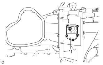
68. REMOVE TRANSMISSION OIL COOLER ASSEMBLY
Click here
69. REMOVE HYBRID VEHICLE TRANSAXLE ASSEMBLY
Click here
70. FIX ENGINE ASSEMBLY
(a) Using wooden blocks or plate lift attachments, set the engine on a flat surface.
NOTICE:
- Place wooden blocks or plate lift attachments so that the engine is level.
- Never install attachments to the oil pan sub-assembly of the engine assembly or transaxle as doing so may deform the oil pan.
- Perform this step while supporting the engine assembly using a sling device and chain block.
71. REMOVE TRANSMISSION INPUT DAMPER ASSEMBLY
Click here
72. REMOVE FLYWHEEL SUB-ASSEMBLY
Click here
73. REMOVE ENGINE WIRE
74. INSTALL ENGINE TO ENGINE STAND
NOTICE:
- Pay attention to the angle of the sling device as the engine assembly or engine hangers may be damaged or deformed if the angle is incorrect.
- With the exception of installing the engine assembly to an engine stand or removing the engine assembly from an engine stand, do not perform any work on the engine while it is suspended, as doing so is dangerous.
(a) Install the engine to an engine stand with the bolts.
(b) Remove the 2 bolts and 2 engine hangers.
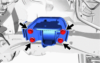
75. REMOVE REAR ENGINE MOUNTING INSULATOR
HINT:
Perform this procedure only when replacement of the rear engine mounting insulator is necessary.
| (a) Remove the 2 bolts, 2 nuts and rear engine mounting insulator. |
|
76. REMOVE ENGINE MOUNTING INSULATOR SUB-ASSEMBLY RH
HINT:
Perform this procedure only when replacement of the engine mounting insulator sub-assembly RH is necessary.
| (a) Remove the bolt and radiator reservoir bracket. |
|
(b) Remove the 3 bolts and engine mounting insulator sub-assembly RH.
77. REMOVE ENGINE MOUNTING SPACER
HINT:
Perform this procedure only when replacement of the engine mounting spacer is necessary.
| (a) Remove the 2 bolts and engine mounting spacer. |
|
78. REMOVE ENGINE MOUNTING INSULATOR LH
HINT:
Perform this procedure only when replacement of the engine mounting insulator LH is necessary.
| (a) Remove the 4 bolts and engine mounting insulator LH. |
|
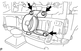
79. REMOVE DRIVE SHAFT BEARING BRACKET
| (a) Remove the 3 bolts and drive shaft bearing bracket. |
|
READ NEXT:
 Installation
INSTALLATION CAUTION / NOTICE / HINT CAUTION: As the engine assembly with transaxle is extremely heavy, the engine lifter may suddenly drop if the instructions listed in the repair manual are not foll
Precaution
PRECAUTION HINT:
Any digits beyond the 0.01 mm (1/1000 in.) place for standard, minimum and maximum values should be used as a reference only.
When both standard and maximum or minimum values are
SEE MORE:
Removal
REMOVAL CAUTION / NOTICE / HINT PROCEDURE 1. REMOVE ELECTRIC POWER STEERING COLUMN SUB-ASSEMBLY Click here 2. REMOVE POWER STEERING ECU ASSEMBLY (a) Detach the claw and remove the power steering ECU protector from the power steering ECU assembly. (b) Remove the 2 cable ties and h
PIG Power Supply Voltage (C1552,C1554)
DESCRIPTION When a problem occurs in the power steering system, the power source relay circuit is shut off to stop the power assist. DTC No. Detection Item DTC Detection Condition Trouble Area Warning Indicate Return-to-normal Condition Note C1552 PIG Power Supply Voltage PIG
