Lexus NX: Cooling Fan Ecu
On-vehicle Inspection
ON-VEHICLE INSPECTION
PROCEDURE
1. INSPECT COOLING FAN ECU
(a) Check and ensure the following conditions:
(1) The power switch is off.
(2) The engine coolant temperature is less than 92°C (198°F).
(3) The auxiliary battery voltage is between 11 and 14 V.
(4) The A/C switch is off.
(b) Connect the pickup of a clamp-on ammeter around 1 of the 2 wires for the cooling fan motor.
(c) Turn the power switch on (IG) and wait for approximately 10 seconds. Check that the fan does not operate.
(d) Put the engine in inspection mode (maintenance mode).
Click here .gif)
(e) Start the engine. Check that the fan does not operate with the engine idling.
HINT:
- Make sure that the engine coolant temperature is less than 92°C (198°F).
- Turn the A/C switch off.
(f) Check that the fan operates when the A/C switch is turned on.
Standard Current:
| Item | Condition | Specified Condition |
|---|---|---|
| Cooling fan motor | Auxiliary battery voltage applied at 20°C (68°F) | 4.0 to 20.0 A |
| No. 2 cooling fan motor | 4.0 to 20.0 A |
HINT:
Make sure that the engine coolant temperature is less than 92°C (198°F).
(g) Check that the fan operates when the engine coolant temperature sensor connector is disconnected.
Standard Current:
| Item | Condition | Specified Condition |
|---|---|---|
| Cooling fan motor | Auxiliary battery voltage applied at 20°C (68°F) | 4.0 to 20.0 A |
| No. 2 cooling fan motor | 4.0 to 20.0 A |
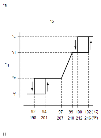
| (h) After the engine is warmed up, check that the fan operates as shown in the illustration. HINT:
|
|
READ NEXT:
 Components
COMPONENTS ILLUSTRATION *1 COOLING FAN ECU *2 COOLING FAN MOTOR *3 COOLING FAN WIRE *4 FAN *5 NO. 2 COOLING FAN MOTOR *6 NO. 2 FAN *7 COOLING FAN MOTOR INSULATOR
On-vehicle Inspection
ON-VEHICLE INSPECTION PROCEDURE 1. INSPECT COOLING FAN MOTOR (a) Disconnect the cooling fan motor connector. (b) Check that the fan rotates smoothly by hand. (c) Check that the cooling fan motor tu
SEE MORE:
Diagnostic Trouble Code Chart
DIAGNOSTIC TROUBLE CODE CHART Power Door Lock Control System DTC No. Detection Item Link B1243 GSW Terminal Circuit Malfunction
Removal
REMOVAL PROCEDURE 1. REMOVE NO. 1 ENGINE UNDER COVER ASSEMBLY Click here 2. DISCONNECT TRANSMISSION CONTROL CABLE ASSEMBLY (a) Remove the nut and disconnect the transmission control cable assembly from the control shaft lever. (b) Remove the clip from the transmission control cabl
