Lexus NX: Installation
INSTALLATION
CAUTION / NOTICE / HINT
NOTICE:
- The type of battery voltage sensor to be used varies depending on the vehicle model.
- If the wrong type of battery voltage sensor is installed, the power switch cannot be turned on (READY).
-
After installing the battery voltage sensor, perform the following to check that the power switch can be turned on (READY).
- Turn the power switch on (READY).
- Turn the power switch off and wait for 30 seconds or more.
- Turn the power switch on (READY) again.
PROCEDURE
1. INSTALL BATTERY VOLTAGE SENSOR
CAUTION:
Wear insulated gloves and use insulated tools.
| (a) Install the battery voltage sensor with the 4 nuts. Torque: 7.5 N·m {76 kgf·cm, 66 in·lbf} |
|
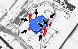
(b) Connect the 3 battery voltage sensor connectors.
NOTICE:
The connectors should be connected securely.
2. INSTALL LOWER NO. 2 HYBRID BATTERY CARRIER PATCH
CAUTION:
Wear insulated gloves and use insulated tools.
| (a) Install the lower No. 2 hybrid battery carrier patch with the 3 nuts and bolt. Torque: 7.5 N·m {76 kgf·cm, 66 in·lbf} |
|
.png)
(b) Connect the wire harness clamp.
3. INSTALL HV BATTERY JUNCTION BLOCK ASSEMBLY
Click here .gif)
READ NEXT:
 On-vehicle Inspection
ON-VEHICLE INSPECTION PROCEDURE 1. INSPECT FOR COOLANT LEAK (for Inverter Coolant) (a) Remove the inverter reserve tank cap. CAUTION: To avoid the danger of being burned, do not remove the inverter re
Replacement
REPLACEMENT PROCEDURE 1. REMOVE NO. 1 ENGINE UNDER COVER Click here 2. DRAIN COOLANT (for Inverter Coolant) NOTICE: Collect the drained coolant and measure its volume to establish a benchmark. Whe
SEE MORE:
Components
COMPONENTS ILLUSTRATION *A w/ Woofer *B w/o Woofer *C w/o Power Back Door *D w/ Power Back Door *1 BACK DOOR CENTER GARNISH *2 BACK DOOR FINISH COVER LH *3 BACK DOOR FINISH COVER RH *4 BACK DOOR LOCK COVER *5 BACK DOOR SIDE GARNISH LH *6 BACK DOOR SI
Installation
INSTALLATION PROCEDURE 1. INSTALL AUTOMATIC LIGHT CONTROL SENSOR (a) Attach the 2 claws to install the automatic light control sensor. 2. INSTALL NO. 1 SPEAKER OPENING COVER ASSEMBLY Click here 3. INSPECT AUTOMATIC LIGHT CONTROL SYSTEM for Single Beam Headlight: Click here for Triple Beam He
© 2016-2026 Copyright www.lexunx.com
