Lexus NX: Removal
REMOVAL
PROCEDURE
1. PRECAUTION
Click here .gif)
2. REMOVE SERVICE PLUG GRIP
Click here
3. DRAIN COOLANT (for Inverter Coolant)
Click here
4. DISCONNECT WIRE HARNESS
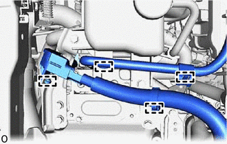
| (a) Disconnect the 4 wire harness clamps from the inverter reserve tank assembly and inverter with converter assembly. |
|
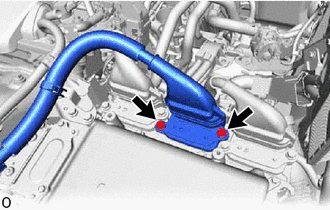
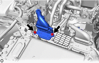
5. REMOVE INVERTER RESERVE TANK ASSEMBLY
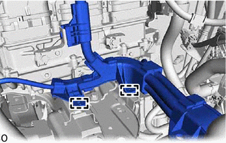
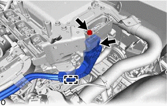
| (a) Slide the hose clamp, and disconnect the water hose from the inverter reserve tank assembly. |
|
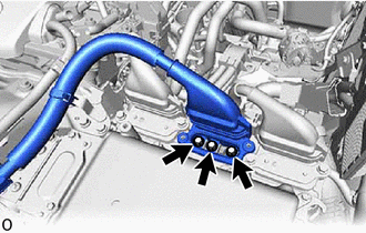
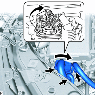
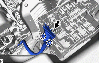
(b) Remove the 2 bolts, and disconnect the inverter reserve tank assembly from the inverter reserve tank bracket.
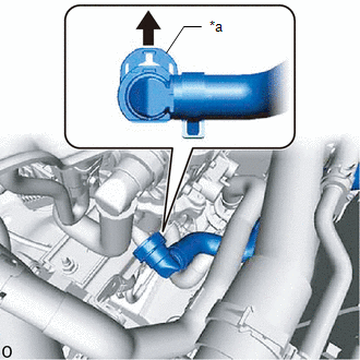
(c) Slide the retainer as shown in the illustration, disconnect the No. 1 inverter cooling hose assembly, and remove the inverter reserve tank assembly.
NOTICE:
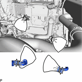
Cover the disconnected water hose and pipe with a plastic bag and tape to prevent coolant from splattering.
HINT:
Turn the quick connector to the left, then release the retainer to prevent it from interfering with the inverter bracket.
6. REMOVE CONNECTOR COVER ASSEMBLY
CAUTION:
Be sure to wear insulated gloves.
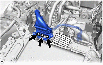
| (a) Using an insulated tool, remove the 2 bolts and connector cover assembly. NOTICE:
|
|
.png)
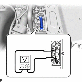
7. CHECK TERMINAL VOLTAGE
| (a) Using a voltmeter, measure the voltage between the terminals of the 2 phase connectors. Standard voltage: 0 V HINT: Use a measuring range of DC 750 V or more on the voltmeter. |
|
8. TEMPORARILY INSTALL CONNECTOR COVER ASSEMBLY
| (a) Temporarily install the connector cover assembly with the bolt to prevent any foreign objects or water from entering the inverter with converter. |
|
9. REMOVE RADIATOR SUPPORT OPENING COVER
Click here
10. REMOVE AIR CLEANER CAP SUB-ASSEMBLY
Click here
11. REMOVE AIR CLEANER FILTER ELEMENT SUB-ASSEMBLY
Click here
12. REMOVE AIR CLEANER CASE SUB-ASSEMBLY
Click here
13. REMOVE UPPER INVERTER COVER
CAUTION:
Be sure to wear insulated gloves.
| (a) Using an insulated tool, remove the 2 bolts and upper inverter cover (generator cable side). NOTICE:
|
|
14. DISCONNECT GENERATOR CABLE
CAUTION:
Be sure to wear insulated gloves.
NOTICE:
Before replacing the wire harness boot, check if any DTCs are output.
| (a) Using an insulated tool, remove the 3 bolts. |
|
| (b) Disconnect the wire harness clamp and generator cable from the inverter bracket. NOTICE:
|
|
| (c) Cut the Tie Band, and remove the insulating tape from the wire harness boot. NOTICE: When removing the Tie Band and the insulating tape, be careful not to damage the wire harness boot and generator cable. |
|
(d) Remove the wire harness boot.
15. REMOVE UPPER INVERTER COVER
CAUTION:
Be sure to wear insulated gloves.
| (a) Using an insulated tool, remove the 2 bolts and upper inverter cover (motor cable side). NOTICE:
|
|
16. DISCONNECT MOTOR CABLE
| (a) Using an insulated tool, remove the 3 bolts. |
|
(b) Disconnect the wire harness clamp and the motor cable from the inverter bracket.
NOTICE:
- When disconnecting, do not damage the terminals, connector housing and inverter with converter assembly.
- Do not touch the connector rubber seal and terminal.
- Wrap insulation tape around the removed terminals to insulate them.
- Cover the hole with non-residue tape to prevent entry of foreign matter or water after removing the cable.
17. REMOVE UPPER INVERTER COVER
CAUTION:
Be sure to wear insulated gloves.
| (a) Using an insulated tool, remove the 2 bolts and upper inverter cover (rear motor high-voltage cable side). NOTICE:
|
|
18. REMOVE NO. 2 FRAME WIRE
NOTICE:
Before replacing the wire harness boot, check if any DTCs are output.
CAUTION:
Be sure to wear insulated gloves.
| (a) Using an insulated tool, remove the 3 bolts. |
|
| (b) Detach the 2 clamps. |
|
| (c) Disconnect the wire harness clamp and the No. 2 frame wire (rear motor high-voltage cable side) from the air cleaner bracket. NOTICE:
|
|
| (d) Cut the Tie Band, and remove the insulating tape from the wire harness boot. NOTICE: When removing the Tie Band and the insulating tape, be careful not to damage the wire harness boot and No. 2 frame wire. |
|
(e) Remove the wire harness boot.
19. REMOVE CONNECTOR COVER ASSEMBLY
CAUTION:
Be sure to wear insulated gloves.
| (a) Remove the bolt and connector cover assembly. NOTICE:
|
|
20. DISCONNECT ENGINE WIRE
CAUTION:
Be sure to wear insulated gloves.
| (a) Disconnect the engine wire connector from the inverter with converter assembly. NOTICE:
|
|
21. DISCONNECT NO. 2 FRAME WIRE
CAUTION:
Be sure to wear insulated gloves.
| (a) Remove the bolt. |
|
(b) Remove the clamp and disconnect the No. 2 frame wire.
NOTICE:
- When disconnecting, do not damage the terminals, connector housing and inverter with converter assembly.
- Do not touch the connector rubber seal and terminal.
- Wrap insulation tape around the removed terminals to insulate them.
- Cover the hole with non-residue tape to prevent entry of foreign matter or water after removing the cable.
22. TEMPORARILY INSTALL CONNECTOR COVER ASSEMBLY
CAUTION:
Be sure to wear insulated gloves.
(a) Temporarily install the connector cover assembly with the bolt to prevent any foreign objects or water from entering the inverter with converter assembly.
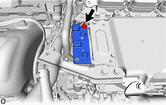
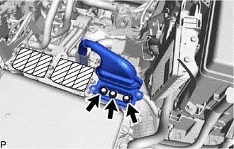
23. REMOVE INVERTER PROTECTOR
| (a) Remove the bolt and inverter protector. |
|
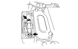
24. DISCONNECT LOW VOLTAGE CONNECTOR
| (a) Lift up the lock lever, and disconnect the 3 low voltage connectors. NOTICE:
|
|
25. DISCONNECT NO. 3 ENGINE ROOM WIRE
(a) Remove the relay block cover.
| (b) Remove the nut from the No. 3 engine room wire. |
|
(c) Attach the 2 claws, and disconnect the No. 3 engine room wire from the junction block.
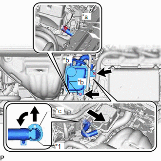
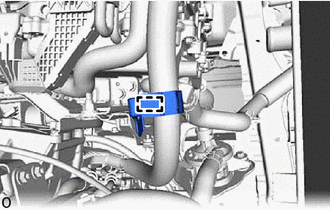
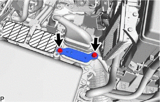
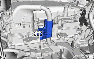
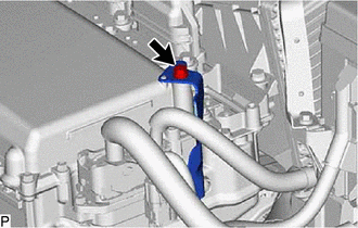
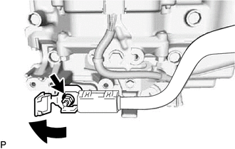
26. DISCONNECT NO. 2 INVERTER COOLING HOSE ASSEMBLY
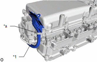
| (a) Slide the retainer in the direction of the arrow shown in the illustration to disconnect the No. 2 inverter cooling hose assembly from the inverter with converter assembly. |
|
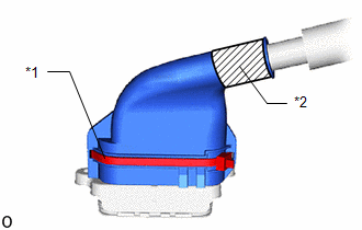
| (b) Plug the pipe and the disconnected hose with vinyl tape, etc. or cover the pipe and hose with plastic bags as shown in the illustration, so that foreign matter does not stick to the union or the inside of the connector and to prevent coolant from spilling near the inverter with converter assembly or enter the cooling path. |
|
27. REMOVE INVERTER WITH CONVERTER ASSEMBLY
CAUTION:
Be sure to wear insulated gloves.
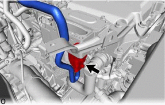
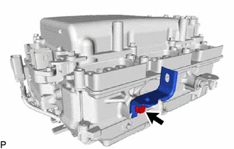
| (a) Temporarily secure the No. 3 engine room wire to the hook on the inverter with converter assembly as shown in the illustration. |
|
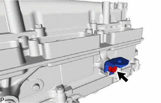
(b) Remove the 2 bolts and No. 6 inverter bracket.
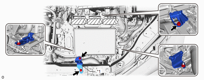
| *1 | No. 6 Inverter Bracket | - | - |
.png) | Bolt | .png) | Nut |
(c) Remove the 2 nuts and bolt and inverter with converter assembly.
NOTICE:
- 2 people are needed to remove the inverter with converter assembly from the vehicle.
- To prevent damage, do not hold the connectors when lifting up the inverter with converter assembly.
- Cover the hole with non-residue tape to prevent entry of foreign matter or water after removing the connector and grommet.
(d) Even after the coolant is drained, coolant remains in the inverter with converter assembly due to its internal structure. Therefore, plug or cover the pipes with plastic bags when removing the inverter with converter assembly from the vehicle so that coolant does not spill out or enter the cooling path.
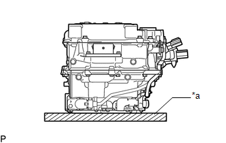
| (e) When removing and storing the inverter with converter assembly, make sure to cover the opening with non-residue tape to prevent foreign matter or water from getting inside, and place a cushioning material under the inverter with converter assembly to protect it. NOTICE: Do not place the inverter with converter assembly upside-down. |
|
28. REMOVE HIGH VOLTAGE FUSE
CAUTION:
Be sure to wear insulated gloves.
HINT:
Perform this procedure only when replacement of the high voltage fuse is necessary.
| (a) Remove the bolt and connector cover assembly. NOTICE:
|
|
| (b) Remove the 2 nuts and high voltage fuse. |
|
(c) Temporarily install the connector cover assembly with the bolt to prevent any foreign objects or water from entering the inverter with converter assembly.
29. REMOVE NO. 1 AIR CLEANER BRACKET
| (a) Remove the bolt and No. 1 air cleaner bracket. |
|
30. REMOVE AIR CLEANER BRACKET
| (a) Remove the bolt and air cleaner bracket. |
|
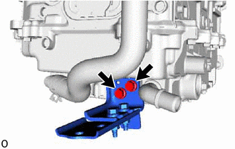
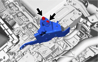
31. REMOVE NO. 4 INVERTER BRACKET
| (a) Remove the 2 bolts and No. 4 inverter bracket. |
|
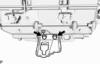
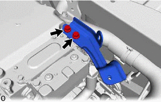
32. REMOVE NO. 2 INVERTER BRACKET
| (a) Remove the 2 bolts and No. 2 inverter bracket. |
|
33. REMOVE NO. 3 INVERTER BRACKET
| (a) Remove the 2 bolts and No. 3 inverter bracket. |
|
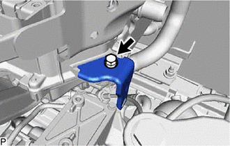
34. REMOVE WIRE HARNESS CLAMP BRACKET
| (a) Remove the bolt and wire harness clamp bracket. |
|
35. REMOVE HYBRID INVERTER PROTECTOR ASSEMBLY
| (a) Remove the 2 bolts and hybrid inverter protector assembly. |
|
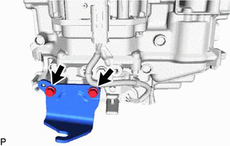
36. REMOVE NO. 2 INVERTER RESERVE TANK BRACKET
| (a) Remove the 2 bolts and No. 2 inverter reserve tank bracket. |
|
37. REMOVE NO. 3 ENGINE ROOM WIRE
| (a) Open the terminal cap. NOTICE: Do not exert unnecessary force when twisting the terminal cap open. |
|
(b) Remove the nut and No. 3 engine room wire.
READ NEXT:
 Installation
INSTALLATION CAUTION / NOTICE / HINT NOTICE:
When replacing with a new inverter with converter assembly, securely lock the retainer of the inverter cooling hose since it is not locked.
Before rep
Relay
On-vehicle InspectionON-VEHICLE INSPECTION PROCEDURE 1. INSPECT IGNITION CONTROL RELAY (IGCT) (a) Measure the resistance according to the value(s) in the table below. Standard Resistance: Test
SEE MORE:
Procedure
PROCEDURE PROCEDURE 1. CUSTOMIZE DYNAMIC RADAR CRUISE CONTROL SYSTEM Click here 2. CUSTOMIZE LANE TRACING ASSIST SYSTEM Click here 3. CUSTOMIZE ROAD SIGN ASSIST SYSTEM Click here 4. CUSTOMIZE ADAPTIVE VARIABLE SUSPENSION SYSTEM Click here 5. CUSTOMIZE POWER TILT AND POWER TELESCOPIC STEERING
Open or Short Circuit in Motor (C13A6)
DESCRIPTION DTC No. Detection Item DTC Detection Condition Trouble Area Memory Note C13A6 Open or Short Circuit in Motor Both of following conditions are met:
Power switch on (IG) or electric parking brake switch (integration control and panel assembly) pulled to lock side wi
