Lexus NX: Removal
REMOVAL
PROCEDURE
1. REMOVE BACK DOOR CENTER GARNISH
Click here 
2. REMOVE BACK DOOR SIDE GARNISH LH
Click here
3. REMOVE BACK DOOR SIDE GARNISH RH
Click here
4. REMOVE BACK DOOR TRIM BASE (w/ Power Back Door)
Click here
5. REMOVE PULL HANDLE (w/ Power Back Door)
Click here
6. REMOVE BACK DOOR FINISH COVER LH (w/o Power Back Door)
Click here
7. REMOVE BACK DOOR FINISH COVER RH (w/o Power Back Door)
Click here
8. REMOVE BACK DOOR LOCK COVER (w/ Power Back Door)
Click here
9. REMOVE BACK DOOR LOCK COVER (w/o Power Back Door)
Click here
10. REMOVE BACK DOOR TRIM BOARD ASSEMBLY
Click here
11. REMOVE NO. 1 AMPLIFIER ANTENNA ASSEMBLY
| (a) Disconnect the 2 connectors and remove the bolt. |
|
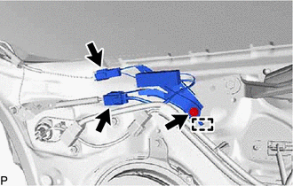
(b) Detach the guide and remove the No. 1 amplifier antenna assembly.
READ NEXT:
 Installation
INSTALLATION PROCEDURE 1. INSTALL NO. 1 AMPLIFIER ANTENNA ASSEMBLY (a) Attach the guide and install the No. 1 amplifier antenna assembly with the bolt. Torque: 8.3 N·m {85 kgf·cm, 73 in·lbf} (b) C
Components
COMPONENTS ILLUSTRATION *1 DECK FLOOR BOX LH *2 NO. 3 DECK BOARD SUB-ASSEMBLY *3 REAR DECK FLOOR BOX *4 NEGATIVE AUXILIARY BATTERY TERMINAL N*m (kgf*cm, ft.*lbf): Specified
SEE MORE:
Dtc Check / Clear
DTC CHECK / CLEAR CHECK FOR DTC (a) Connect the Techstream to the DLC3. (b) Turn the power switch on (IG). (c) Turn the Techstream on. (d) Enter the following menus: Body Electrical / AFS / Trouble Codes. Body Electrical > AFS > Trouble Codes (e) Check for DTCs. CLEAR DTC (a) Connect the Techs
Installation
INSTALLATION PROCEDURE 1. INSTALL NO. 3 MOTOR WATER JACKET COVER ASSEMBLY Click here 2. INSTALL NO. 1 MOTOR WATER JACKET COVER ASSEMBLY Click here 3. INSTALL NO. 2 MOTOR WATER JACKET COVER ASSEMBLY Click here 4. INSTALL MOTOR CONNECTOR PROTECTOR (a) Apply adhesive to the 2 stud bolts. Adhesive
