Lexus NX: Installation
INSTALLATION
CAUTION / NOTICE / HINT
HINT:
- Use the same procedure for the RH and LH sides.
- The procedure listed below is for the LH side.
PROCEDURE
1. INSTALL SST
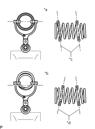
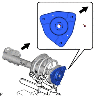
(a) Align the cutout on end of the shock rod of the front shock absorber assembly LH with the installation position.
NOTICE:
Be sure to install the part so that the cutout on the front suspension support sub-assembly LH and the cutout on the shock rod end are aligned.
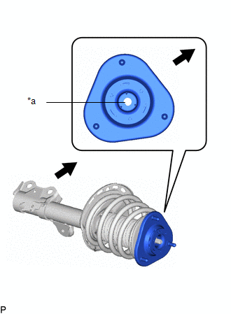
| *a | Cutout |
.png) | Vehicle Exterior |
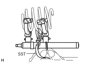
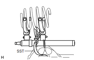
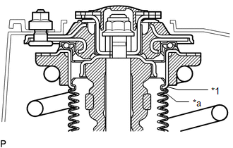
(b) Install SST (09727-58100) and SST (09727-58130) to the front shock absorber assembly LH.
SST: 09727-58100
SST: 09727-58130
SST: 09727-58010
09727-58030
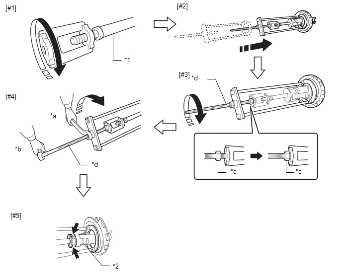
| *1 | Front Shock Absorber Assembly LH | *2 | Shock Absorber Outer Shell |
| *a | Turn | *b | Hold |
| *c | Fixing Nut | *d | Bolt |
NOTICE:
Apply molybdenum grease to the bolt (area with diagonal lines) of SST (09727-58010).
.png)
.png) | Application Area |
(1) Install SST (09727-58030) to the end of the shock rod of the front shock absorber assembly LH.[#1]
(2) Install SST (09727-58010) to the front shock absorber assembly LH.[#2]
NOTICE:
Take due care when installing SST (09727-58010) to ensure the shock rod is not damaged.
(3) Secure the SST (09727-58010) bolt and SST (09727-58030) with the fixing nut.[#3]
(4) After securing the SST (09727-58010) bolt, rotate the nut clockwise.[#4]
HINT:
Extend the shock rod to its maximum length to install SST (09727-58100) and SST (09727-58130).
(5) Using a piece of cloth, etc., clean the shock rod and remove any foreign matter and oil.
NOTICE:
Thoroughly clean the shock rod to prevent damage to the shock rod due to contact of foreign matter.
| (6) Clean the surface of SST (09727-58130) to which the front shock absorber assembly LH is installed and remove any foreign matter and oil. NOTICE: Thoroughly clean the installation surface to prevent damage to the shock rod due to contact of foreign matter. |
|
.png)
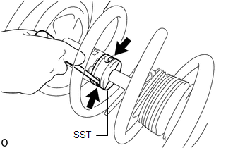
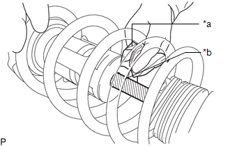
(7) Using a long ball hexagon 5, install SST (09727-58100) and SST (09727-58130) to the shock rod.[#5]
NOTICE:
Before installing, check the position of the cutout on end of the shock rod.
HINT:
Install SST (09727-58100) and SST (09727-58130) to the base of the shock rod and check that SST (09727-58100) and SST (09727-58130) are securing the shock rod.
(8) After securing the SST (09727-58010) bolt, rotate the nut counterclockwise.
(9) Check that the shock rod and SST (09727-58030) have become free before releasing the fixing nut and removing SST (09727-58010) from the shock rod.
NOTICE:
Take due care when removing SST (09727-58010) to ensure the shock rod is not damaged.
(10) Remove SST (09727-58030) from the end of the shock rod.
(11) Using a piece of cloth, etc., clean the end of the shock rod threads and remove any foreign matter and oil.
2. INSTALL FRONT COIL SPRING LOWER INSULATOR LH
| (a) Install the front coil spring lower insulator to the front shock absorber assembly. NOTICE: When installing the insulator, fit the insulator into the depression of the spring seat and insert the positioning pin into the hole. |
|
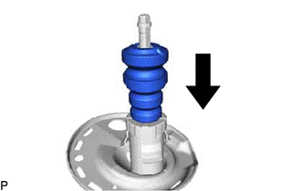
3. INSTALL FRONT SPRING BUMPER LH
| (a) Install the front spring bumper to the front shock absorber assembly. NOTICE: Position the end of the front spring bumper with the smaller diameter downward. |
|
4. INSTALL FRONT COIL SPRING LH
(a) For SST with stopper pins:
.png)
(1) Secure SST in a vise.
SST: 09727-30022
09727-00010
09727-00022
09727-00031
| (2) Attach the hooks of each SST arm across the diameter of the coil spring. CAUTION:
|
|
| (3) Install the stopper pins to the hooks of SST. CAUTION: Make sure that the stopper pins are installed securely. |
|
.png)
(4) Using SST, compress the coil spring.
CAUTION:
- If the coil spring bends while using SST, stop immediately and reattach SST correctly.
- Do not compress the coil spring to the point where the coils touch each other.
- Do not use an impact wrench.
-
If a stopper pin touches the coil spring while using SST, remove the stopper pin and continue with the procedure. In this case, installing the coil spring stopper belt as shown in the illustration is recommended.
SST: 09727-00110
(b) For SST without stopper pins:
| (1) Secure SST in a vise. SST: 09727-30021 09727-00010 09727-00021 09727-00031 |
|
.png)
| (2) Attach the hooks of each SST arm across the diameter of the coil spring. CAUTION:
|
|
(3) Using SST, compress the coil spring.
CAUTION:
- If the coil spring bends while using SST, stop immediately and reattach SST correctly.
- Do not compress the coil spring to the point where the coils touch each other.
- Do not use an impact wrench.
HINT:
Installing SST as shown in the illustration is recommended.
SST: 09727-00110
| (c) Install the front coil spring to the front shock absorber assembly. NOTICE: Make sure to fit the end of the front coil spring that has the larger diameter into the depression of the front lower coil spring insulator. |
|
5. INSTALL FRONT SPRING SEAT SUB-ASSEMBLY WITH INSULATOR LH
| (a) Install the front spring seat sub-assembly with insulator LH to the front shock absorber assembly LH. NOTICE: Make sure that the top end of the insulator (shock absorber dust cover) and the strut bearing are securely attached. |
|
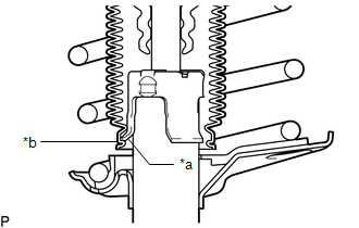
6. INSTALL FRONT SUSPENSION SUPPORT SUB-ASSEMBLY LH
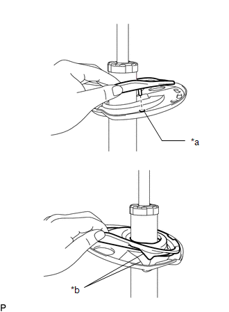
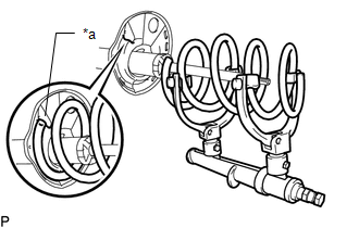
(a) Install the front suspension support sub-assembly as shown in the illustration.
NOTICE:
Check that the slot on the piston rod and the slot on the front suspension support sub-assembly are aligned.
| *a | Slot |
| | Outside of the Vehicle |
7. INSTALL COLLAR
(a) Install the collar to the front shock absorber assembly LH.
8. TEMPORARILY INSTALL FRONT SUPPORT TO FRONT SHOCK ABSORBER NUT
(a) Temporarily install a new front support to front shock absorber nut.
(b) Remove SST from the front coil spring.
NOTICE:
Do not use an impact wrench. It will damage SST.
| (c) Fold back the No. 1 front shock absorber dust cover LH and then use a long ball hexagon 5 to remove SST (09727-58100) and SST (09727-58130) from the front shock absorber assembly LH. NOTICE:
|
|
| (d) Using a piece of cloth, etc., clean the shock rod of the front shock absorber assembly LH and remove any foreign matter and oil. NOTICE: Thoroughly clean the shock rod to prevent damage to the front shock absorber assembly LH due to contact of foreign matter. |
|
9. CONNECT FRONT SPRING SEAT SUB-ASSEMBLY WITH INSULATOR LH
| (a) Connect the end of the insulator of the front spring seat sub-assembly with insulator LH with the claws of the front shock absorber assembly LH. NOTICE:
|
|
10. INSTALL FRONT SUSPENSION SUPPORT PLATE LH
(a) Install the front suspension support plate to the front shock absorber with coil spring.
11. INSTALL FRONT SHOCK ABSORBER WITH COIL SPRING
(a) Install the front shock absorber with coil spring (upper side) and cowl body mounting reinforcement LH with the 3 nuts.
Torque:
50 N·m {510 kgf·cm, 37 ft·lbf}
(b) Connect the front shock absorber with coil spring (lower side) to the steering knuckle with the 2 bolts and 2 nuts.
Torque:
240 N·m {2447 kgf·cm, 177 ft·lbf}
HINT:
The bolts can be installed in either direction, however, make sure that they are both installed in the same direction.
12. TIGHTEN FRONT SUPPORT TO FRONT SHOCK ABSORBER NUT
(a) Tighten the front support to front shock absorber nut.
Torque:
60 N·m {612 kgf·cm, 44 ft·lbf}
13. CONNECT FRONT FLEXIBLE HOSE (w/o AVS)
(a) Connect the front flexible hose to the steering knuckle with the bolt.
Torque:
18.8 N·m {192 kgf·cm, 14 ft·lbf}
14. CONNECT FRONT SKID CONTROL SENSOR WIRE LH (w/ AVS)
Click here .gif)
15. CONNECT FRONT SPEED SENSOR LH (w/ AVS)
Click here
16. CONNECT FRONT SPEED SENSOR LH (w/o AVS)
Click here
17. CONNECT FRONT STABILIZER LINK ASSEMBLY LH
(a) Connect the front stabilizer link assembly to the front shock absorber with coil spring with the nut.
Torque:
74 N·m {755 kgf·cm, 55 ft·lbf}
HINT:
If the ball joint turns together with the nut, use a 6 mm hexagon wrench to hold the stud bolt.
18. INSTALL FRONT SUSPENSION SUPPORT DUST COVER LH
(a) Install the front suspension support dust cover.
19. INSTALL OUTER COWL TOP PANEL
Click here
20. INSTALL FRONT WHEEL
Click here
21. STABILIZE SUSPENSION
(a) Lower the vehicle.
(b) Bounce the vehicle up and down at the corners several times to stabilize the suspension.
22. INSPECT AND ADJUST FRONT WHEEL ALIGNMENT
Click here
23. CHECK FOR SPEED SENSOR SIGNAL
Click here
24. PERFORM INITIALIZATION
Click here
READ NEXT:
 Disposal
DISPOSAL CAUTION / NOTICE / HINT HINT:
Use the same procedure for the RH and LH sides.
The procedure listed below is for the LH side.
PROCEDURE 1. DISPOSE OF FRONT SHOCK ABSORBER ASSEMBLY LH
Components
COMPONENTS ILLUSTRATION *1 FRONT LOWER NO. 1 SUSPENSION ARM SUB-ASSEMBLY LH *2 FRONT STABILIZER BAR *3 FRONT STABILIZER BAR BUSHING LH *4 FRONT STABILIZER BAR BUSHING RH *5 F
SEE MORE:
On-vehicle Inspection
ON-VEHICLE INSPECTION PROCEDURE 1. CHECK FUEL PUMP OPERATION AND INSPECT FOR FUEL LEAK (a) Check fuel pump operation. (1) Connect the Techstream to the DLC3. (2) Turn the power switch on (IG). NOTICE: Do not start the engine. (3) Turn the Techstream on. (4) Enter the following menus: Powertrain / En
Low or High Power Supply Voltage (C1241,C1242)
DESCRIPTION If a malfunction is detected in the power supply circuit, the skid control ECU (brake booster with master cylinder assembly) power source voltage drops, or there is insufficient voltage to operate the ABS main relay, the skid control ECU (brake booster with master cylinder assembly) will
