Lexus NX: Removal
REMOVAL
PROCEDURE
1. FRONT WHEELS FACING STRAIGHT AHEAD
2. SECURE STEERING WHEEL
Click here .gif)
3. REMOVE COLUMN HOLE COVER SILENCER SHEET
Click here
4. DISCONNECT NO. 2 STEERING INTERMEDIATE SHAFT ASSEMBLY
Click here
5. REMOVE FRONT WHEELS
Click here
6. REMOVE NO. 1 ENGINE UNDER COVER ASSEMBLY
Click here
7. REMOVE REAR ENGINE UNDER COVER RH
| (a) Remove the 4 clips and rear engine under cover RH. |
|
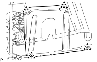
8. REMOVE REAR ENGINE UNDER COVER LH
| (a) Remove the 4 clips and rear engine under cover LH. |
|
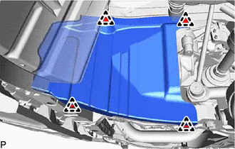
9. REMOVE FRONT CENTER FLOOR COVER LH
Click here
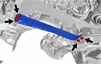
10. REMOVE FRONT SUSPENSION MEMBER REINFORCEMENT LH
| (a) Remove the 4 bolts and front suspension member reinforcement LH. |
|
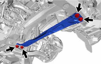
11. REMOVE FRONT SUSPENSION MEMBER REINFORCEMENT RH
| (a) Remove the 4 bolts and front suspension member reinforcement RH. |
|
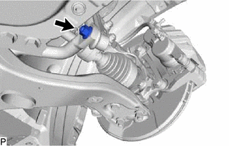
12. DISCONNECT FRONT STABILIZER LINK ASSEMBLY LH
| (a) Remove the nut and disconnect the front stabilizer link assembly LH from the front stabilizer bar. HINT: If the ball joint turns together with the nut, use a 6 mm hexagon wrench to hold the stud bolt. |
|
13. DISCONNECT FRONT STABILIZER LINK ASSEMBLY RH
HINT:
Use the same procedure described for the LH side.
14. DISCONNECT TIE ROD END SUB-ASSEMBLY LH
Click here
15. DISCONNECT TIE ROD END SUB-ASSEMBLY RH
HINT:
Use the same procedure described for the LH side.
16. DISCONNECT FRONT LOWER NO. 1 SUSPENSION ARM SUB-ASSEMBLY LH
Click here
17. DISCONNECT FRONT LOWER NO. 1 SUSPENSION ARM SUB-ASSEMBLY RH
HINT:
Use the same procedure described for the LH side.
18. REMOVE FRONT SUSPENSION MEMBER REAR BRACE LH
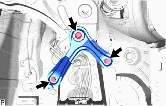
(a) Remove the 3 bolts and front suspension member rear brace LH.
19. REMOVE FRONT SUSPENSION MEMBER REAR BRACE RH
HINT:
Use the same procedure described for the LH side.
20. REMOVE FRONT SUSPENSION CROSSMEMBER SUB-ASSEMBLY
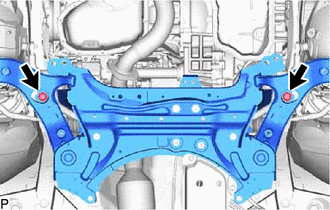
| (a) Remove the 2 bolts and 2 nuts, and disconnect the front suspension crossmember sub-assembly from the rear engine mounting insulator. |
|
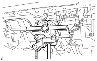
(b) Support the front suspension crossmember sub-assembly with an engine lifter using 4 attachments or equivalent tools as shown in the illustration.
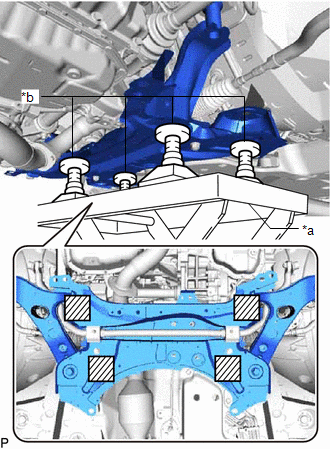
| *a | Engine Lifter |
| *b | Attachment |
.png) | Attachment placement location |
NOTICE:
- Make sure to secure the front suspension crossmember sub-assembly to prevent it from dropping.
- Use the attachments to keep the front suspension crossmember sub-assembly level.
- The front suspension crossmember sub-assembly is a heavy component. Make sure that it is supported securely.
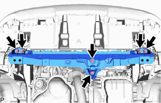
| (c) Remove the 2 bolts and front suspension crossmember sub-assembly. |
|
(d) Slowly lower the front suspension crossmember sub-assembly.
NOTICE:
When lowering the front suspension crossmember sub-assembly, be careful not to damage the vehicle body or other components installed on the vehicle.
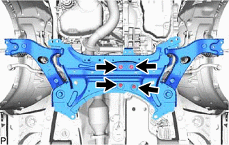
21. REMOVE FRONT CROSSMEMBER SUB-ASSEMBLY
| (a) Using a jack, support the engine and transaxle assembly. |
|
| (b) Remove the 6 bolts and front crossmember sub-assembly. |
|
22. REMOVE STEERING GEAR ASSEMBLY
Click here
23. REMOVE FRONT LOWER NO. 1 SUSPENSION ARM SUB-ASSEMBLY LH
(a) Remove the 2 bolts, nut and front lower No. 1 suspension arm sub-assembly LH from the front suspension crossmember sub-assembly.
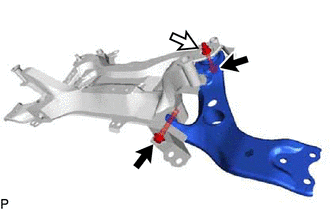
.png) | Bolt |
.png) | Nut |
NOTICE:
Because the nut has its own stopper, do not turn the nut. Loosen the bolt with the nut secured.
24. REMOVE FRONT LOWER NO. 1 SUSPENSION ARM SUB-ASSEMBLY RH
HINT:
Use the same procedure described for the LH side.
25. REMOVE FRONT SUSPENSION MEMBER BRACE
Click here
26. REMOVE FRONT STABILIZER BAR
| (a) Remove the front stabilizer bar with the 2 front stabilizer bar bushings from the front suspension crossmember sub-assembly. |
|
.png)
READ NEXT:
 Installation
INSTALLATION PROCEDURE 1. INSTALL FRONT STABILIZER BAR Click here 2. INSTALL FRONT SUSPENSION MEMBER BRACE Click here 3. TEMPORARILY INSTALL FRONT LOWER NO. 1 SUSPENSION ARM SUB-ASSEMBLY LH (a) Te
Problem Symptoms Table
PROBLEM SYMPTOMS TABLE HINT: Use the table below to help determine the cause of problem symptoms. If multiple suspected areas are listed, the potential causes of the symptoms are listed in order of pr
SEE MORE:
Inspection
INSPECTION PROCEDURE 1. INSPECT FRONT LOWER BALL JOINT ASSEMBLY LH (a) Inspect the turning torque of the ball joint. (1) Secure the front lower ball joint in a vise using aluminum plates. (2) Install the nut to the front lower ball joint stud. (3) Move the stud back and forth several times. Using
Terminals Of Ecu
TERMINALS OF ECU CLOCK ASSEMBLY Terminal No. (Symbol) Wiring Color Terminal Description Condition Specified Condition I163-1 (ILL-) - Body ground G - Body ground Illumination signal ground Power switch on (ACC) Pulse generation I163-2 (E) - Body ground W-B - Body ground
